Wiring substrate with a torsion restrictor for a terminal

a terminal and wiring substrate technology, applied in the field of wiring substrates, can solve the problems of deteriorating reducing the reliability of bonding, and low physical strength, and achieve the effects of reducing the number of torsions of flying leads, reducing the reliability of bonding, and ensuring the extensibility of flying leads

Active Publication Date: 2013-01-10
NHK SPRING CO LTD
View PDF6 Cites 4 Cited by
  • Summary
  • Abstract
  • Description
  • Claims
  • Application Information

AI Technical Summary

Benefits of technology

[0011]To solve the problems of the related art, the present invention provides a wiring substrate capable of securing extensibility of flying leads, suppressing a torsion of the flying leads during a bonding process to an external terminal, and improving reliability of bonding between the flying leads and the external terminal.
[0012]According to an aspect of the present invention, there is provided a wiring substrate including a conductor pattern embedded in an insulating layer, the insulating layer having an opening to expose top and bottom faces of the conductor pattern and define a terminal of the wiring substrate, a torsion restrictor formed in the conductor pattern at a location passing over an edge of the opening, the torsion restrictor restricting torsion of the terminal, and an easily extensible part that is formed on at least one of the torsion restrictor and a portion of the terminal adjoining the torsion restrictor, the easily extensible part allowing the conductor pattern to extend toward the opening in a longitudinal direction.
[0013]According to this aspect of the present invention, the torsion restrictor restricts flying lead, which is the terminal exposed in the opening, from twisting when the flying lead is connected to an external terminal. The easily extensible part allows the conductor pattern to extend when the flying lead is connected to the external terminal, thereby improving reliability of bonding between the flying leads and the external terminal.

Problems solved by technology

The flying leads are thin and narrow, and therefore, are low in physical strength.
Simply providing the flying lead with the wide reinforcing section may prevent a break of the flying lead but may deteriorate the extensibility of the flying lead and decrease reliability of bonding such as bonding strength and connectivity when the flying lead is joined to an external terminal of an external circuit board with ultrasonic bonding.
This problem results in limiting the width of the wide reinforcing section provided for the flying lead.
Therefore, the flying lead may twist to deteriorate reliability of bonding between the flying lead and the external terminal to which the flying lead is joined with ultrasonic bonding.

Method used


Image

  • Wiring substrate with a torsion restrictor for a terminal
  • Wiring substrate with a torsion restrictor for a terminal
  • Wiring substrate with a torsion restrictor for a terminal

Examples


first embodiment

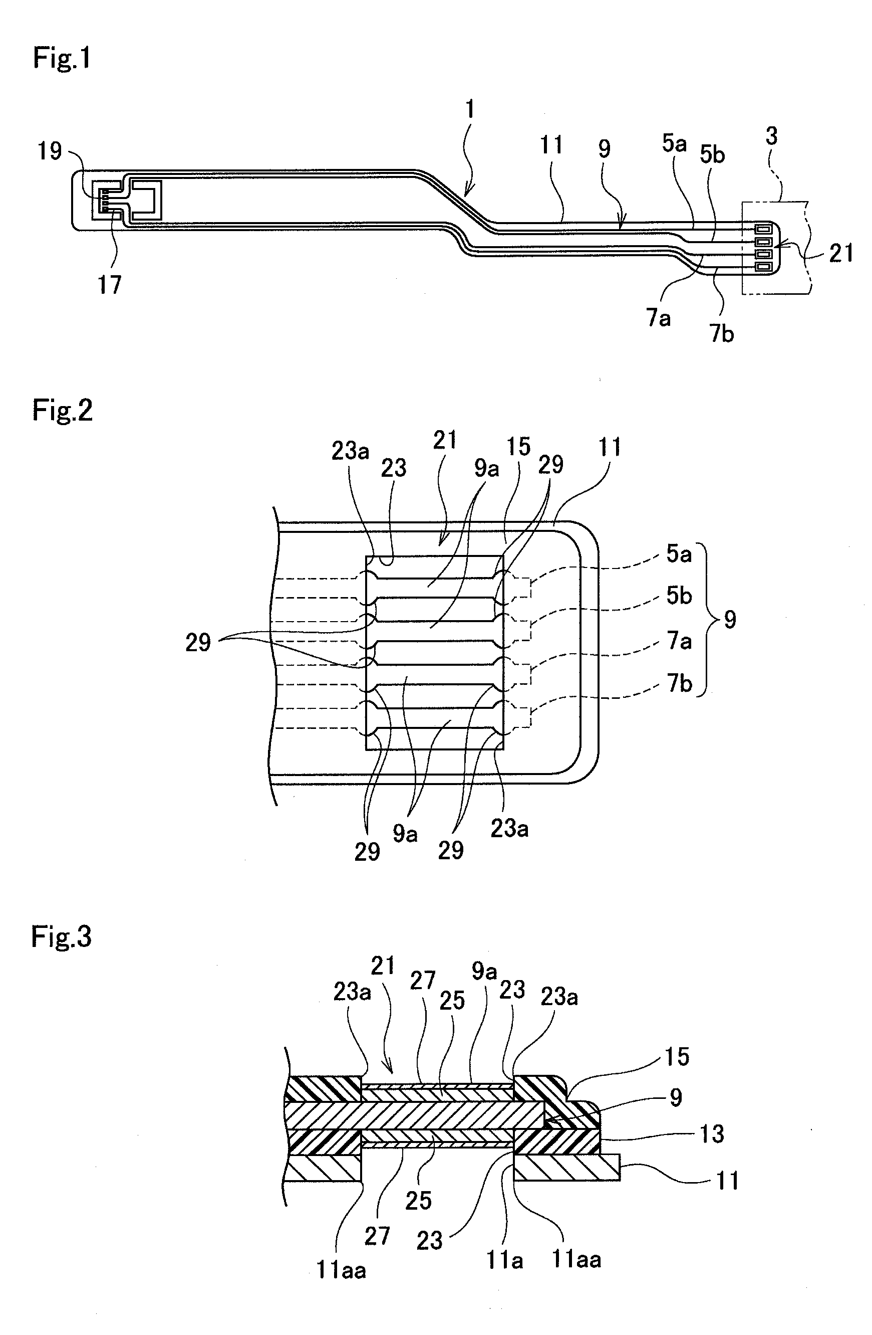
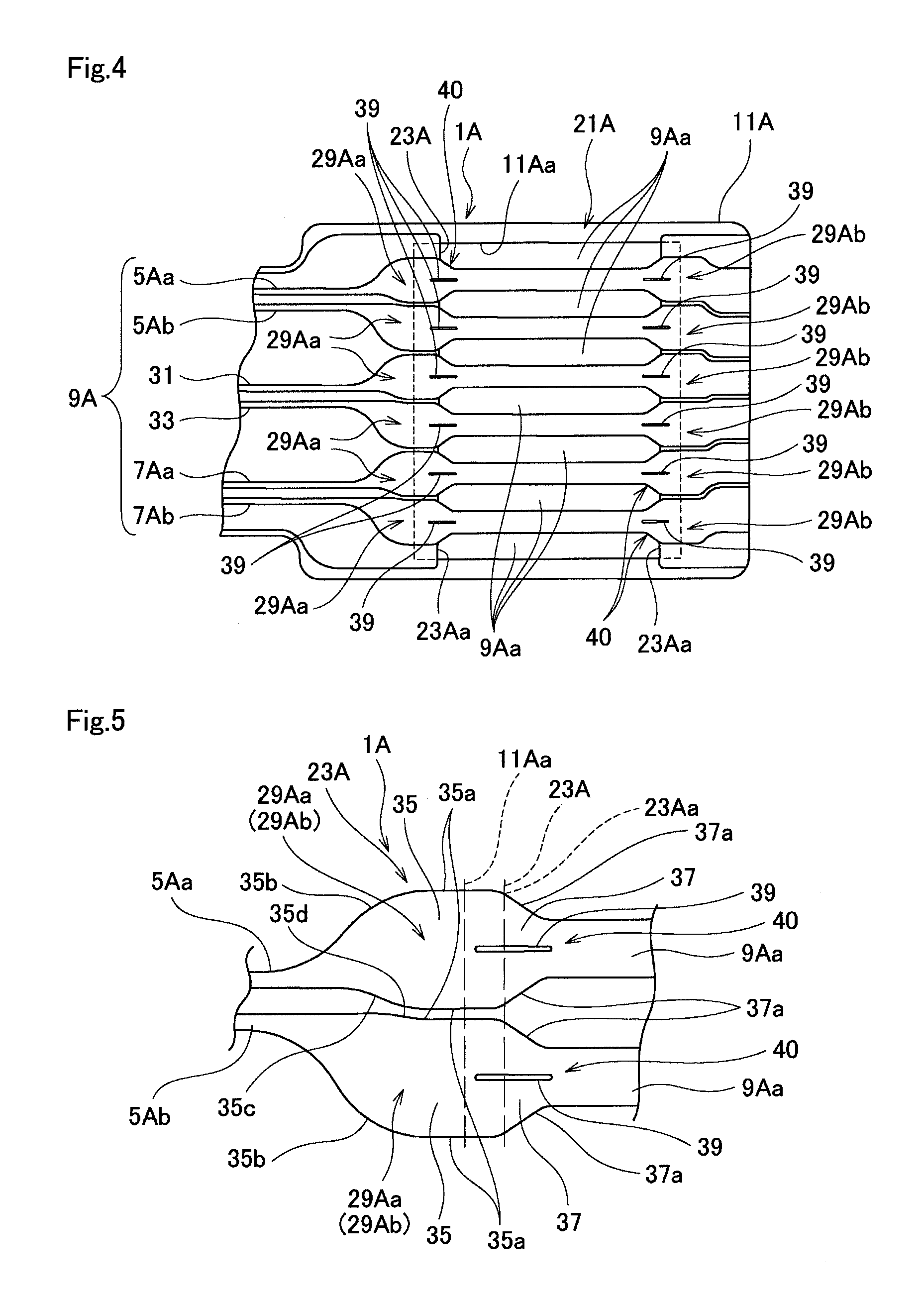
[0044]the present invention will be explained with reference to FIGS. 4 and 5. FIG. 4 is a plan view illustrating a terminal portion of a flexure with a conductor pattern being exposed and FIG. 5 is a plan view illustrating the conductor pattern of FIG. 4.

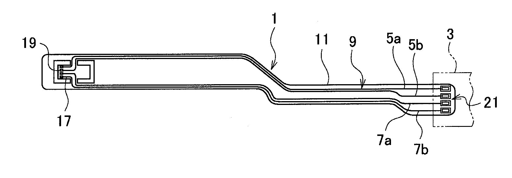
[0045]The flexure 1A according to the first embodiment has the basic structure of the flexure 1 illustrated in FIG. 1, and therefore, like parts are represented with like reference numerals plus “A” in FIGS. 4 and 5 to omit overlapping explanations. At a rear end, the flexure 1A as a wiring substrate has a terminal portion 21A to be connected to an external circuit board. The terminal portion 21A according to the first embodiment is applicable to other flexure with other basic structure.

[0046]The flexure 1A has a support layer 11A that is a thin plate made of metal such as stainless steel and is longitudinally extended, an insulating base layer 13A formed on the support layer 11A, a wiring pattern 9A as a conductor pattern formed o...

second embodiment

[0062] the flexure 1B has an easily extensible part 40B including two slits 39B that are parallel to each other and are positioned so as to equally divide the width of a flying lead 9Ba into three. The length of the slits 39B is optional.

[0063]The second embodiment allows a part between the flying lead 9Ba and a wide part 35B to more easily extend, thereby improving reliability of bonding between the flying leads 9Ba and external terminals of an external circuit board when they are connected to each other with ultrasonic waves.

[0064]In addition, the second embodiment provides the same effects as the first embodiment.

[0065]A third embodiment of the present invention will be explained with reference to FIG. 7. FIG. 7 is a plan view illustrating a conductor pattern at a terminal portion of a flexure. The third embodiment is similar to the second embodiment, and therefore, like parts are represented with like reference numerals plus “C” in FIG. 7 instead of “B” of FIG. 6 to omit overlap...

third embodiment

[0066] the flexure 1C has an easily extensible part 40C including two linear slits 39C that are inclined so that first ends thereof equally divide the width of a flying lead 9Ca into three and second ends thereof nearly equally divide a wide part 35C into three. The length of the slits 39C is optional.

[0067]The third embodiment allows a part between the flying lead 9Ca and the wide part 35C to easily extend, thereby improving reliability of bonding between the flying leads 9Ca and external terminals of an external circuit board when they are connected to each other with ultrasonic waves.

[0068]In addition, the third embodiment provides the same effects as the second embodiment.

[0069]A fourth embodiment of the present invention will be explained with reference to FIG. 8. FIG. 8 is a plan view illustrating a conductor pattern at a terminal portion of a flexure. The fourth embodiment is similar to the first embodiment, and therefore, like parts are represented with like reference numera...


PUM

PropertyMeasurementUnit
widthaaaaaaaaaa
capacitanceaaaaaaaaaa
speedaaaaaaaaaa

Abstract

A wiring substrate comprises a conductor pattern embedded in an insulating layer, the insulating layer having an opening to expose top and bottom faces of the conductor pattern and define a terminal of the wiring substrate, a torsion restrictor formed in the conductor pattern at a location passing over an edge of the opening, the torsion restrictor restricting torsion of the terminal, and an easily extensible part formed on at least one of the torsion restrictor and a portion of the terminal adjoining the torsion restrictor, the easily extensible part allowing the conductor pattern to longitudinally extend toward the opening.

Description

BACKGROUND OF THE INVENTION[0001]1. Field of the Invention[0002]The present invention relates to a wiring substrate such as a flexure that provides a head suspension incorporated in a hard disk drive with wiring.[0003]2. Description of Related Art[0004]Due to the widely spreading Internet and surging information, recent personal computers are required to process a large amount of data at high speed and hard disk drives incorporated in the personal computers are required to increase storage capacity and data transmission speed. Accordingly, a head suspension to write and read data to and from a disk in the hard disk drive must employ a highly functional flexure.[0005]The flexure generally includes read wiring, write wiring, and a terminal on a tail part to be connected to a main circuit board.[0006]To connect the terminal of the flexure to the main circuit board, there are roughly two techniques. One technique forms flying leads at the terminal of the flexure and joins the flying lea...

Claims


Application Information

Patent Timeline
Patent Type & Authority Applications(United States)
IPC IPC(8): G11B5/48
CPCH05K1/056G11B5/486H05K2201/0969H05K3/4007
Inventor YAMADA, YUKIEYAMAGUCHI, NAOKI
Owner NHK SPRING CO LTD
Why Eureka
Try Eureka