

Shutter control device
- Summary
- Abstract
- Description
- Claims
- Application Information
AI Technical Summary
Benefits of technology
Problems solved by technology
Method used
Image

Examples
first embodiment
[0025]the present invention will be described below with reference to the drawings.
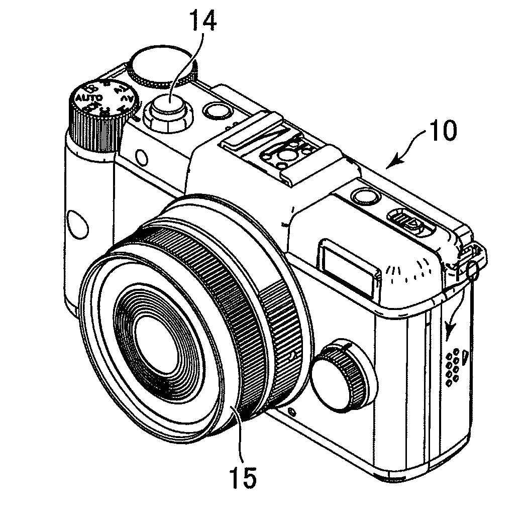
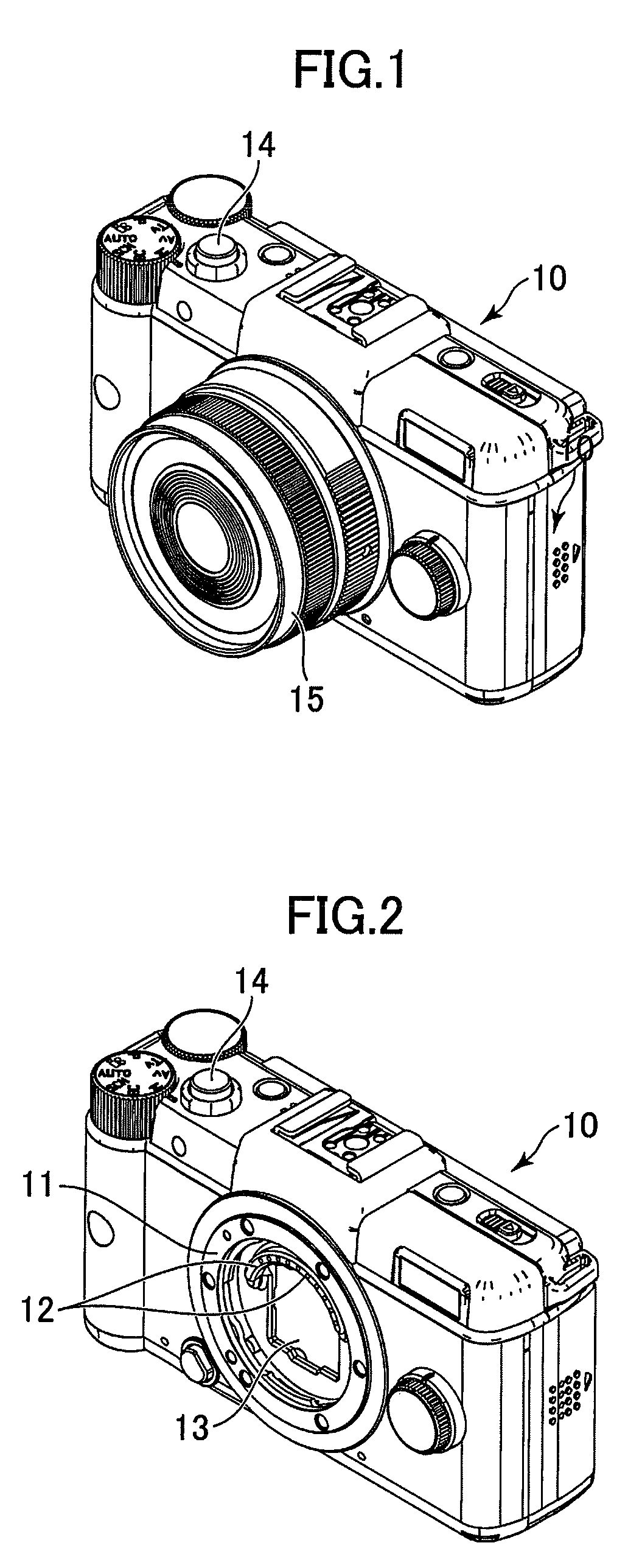
[0026]FIG. 1 shows an external appearance of a camera with an interchangeable lens, and FIG. 2 shows the camera without a lens barrel 15, which has been removed from its camera body 10. In this camera system the lens barrel 15 is detachably attached to the camera body 10. A shutter is provided in the lens barrel 15, and a shutter operation is performed by a camera processor provided in the camera body 10, as described below. In this embodiment the shutter is usually open, and is closed by a shutter release.
[0027]A plurality of electrical contacts 12 are disposed in the form of an arch in the inside of a lens mount 11 of the camera body 10. An imaging device unit 13, in which an imaging device (not shown) is housed, is provided under the electrical contacts 12. When electrical power of the camera body 10 is turned on, moving images are obtained through the imaging device and can be displayed on a monit...
second embodiment
[0060]Next, a second embodiment is described.
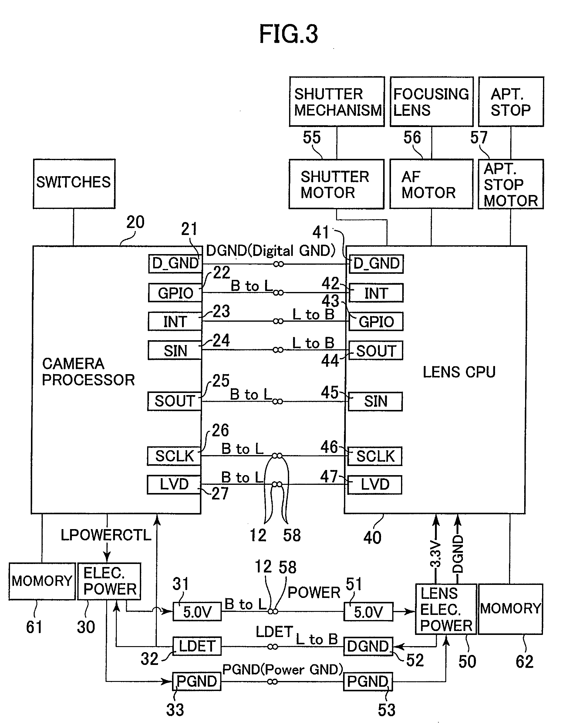
[0061]The shutter delay table is read out in the lens initialization routine (Step 101 of FIG. 7) and a delay time is calculated for each photographing operation in the camera processor 20 in the first embodiment. Conversely, in the second embodiment, instead of storing the shutter delay table to the memory 61 of the camera body 10, the delay time data is transmitted directly from the lens CPU 40 to the camera processor 20. Namely, in the communication process mode the CPU 40 obtains the necessary time delay information by merely referring to the shutter delay table based on the aperture value output from the camera processor 20. The time delay information is then output to the camera processor 20 during photography. The other constructions are identical to those of the first embodiment.
[0062]FIG. 12 shows a flowchart for a lens initiation routine in the second embodiment. The difference from the first embodiment is that Step 112 has been...
PUM
 Abstract
Description
Claims
Application Information