Transcutaneous Joint Unloading Device and Method

a technology of unloading device and joint, which is applied in the field of joint unloading device, can solve the problems of requiring substantial recovery periods, requiring high recovery time, and arthroplasty procedures are also characterized by relatively long recovery times, and none of these currently available therapies are chondroprotective, so as to reduce pain and cushion the joint from excessive loading

Active Publication Date: 2013-01-10
MOXIMED INC
View PDF4 Cites 28 Cited by
  • Summary
  • Abstract
  • Description
  • Claims
  • Application Information

AI Technical Summary

Benefits of technology

[0006]One new approach to treating osteoarthritis involves implantation of an extra-articular implantable joint unloading device which is positioned alongside the painful joint and bears some of the load normally borne by the joint. This unloading device reduces pain by cushioning the joint from excessive loading. Since the device is extra-capsular and extra-articular, no bone, ligament, or cartilage is removed and future treatment options, such as joint replacement, are still available if needed. However, for some patients a more temporary solution may be more attractive. Patients and physicians may also be interested in providing an unloading device in which a portion of the device is external for ease of adjustment and removal.

Problems solved by technology

Such procedures are a last resort treatment as they are highly invasive and require substantial periods of recovery.
As with joint replacement, these other arthroplasty procedures are also characterized by relatively long recovery times and are highly invasive procedures.
Because of this, none of these currently available therapies are chondro-protective.
If the load falls below the nominal range for extended periods of time, bone and cartilage can become softer and weaker (atrophy).
Finally, if the load rises too high, then abrupt failure of bone, cartilage and other tissues can result.
Accordingly, it has been concluded that the treatment of osteoarthritis and other bone and cartilage conditions is severely hampered when a surgeon is not able to precisely control and prescribe the levels of joint load.
A number of these approaches have had some success in alleviating pain but have ultimately been unsuccessful due to patient discomfort or the inability of the devices to facilitate and support the natural motion and function of the diseased joint.

Method used


Image

  • Transcutaneous Joint Unloading Device and Method
  • Transcutaneous Joint Unloading Device and Method
  • Transcutaneous Joint Unloading Device and Method

Examples


Embodiment Construction

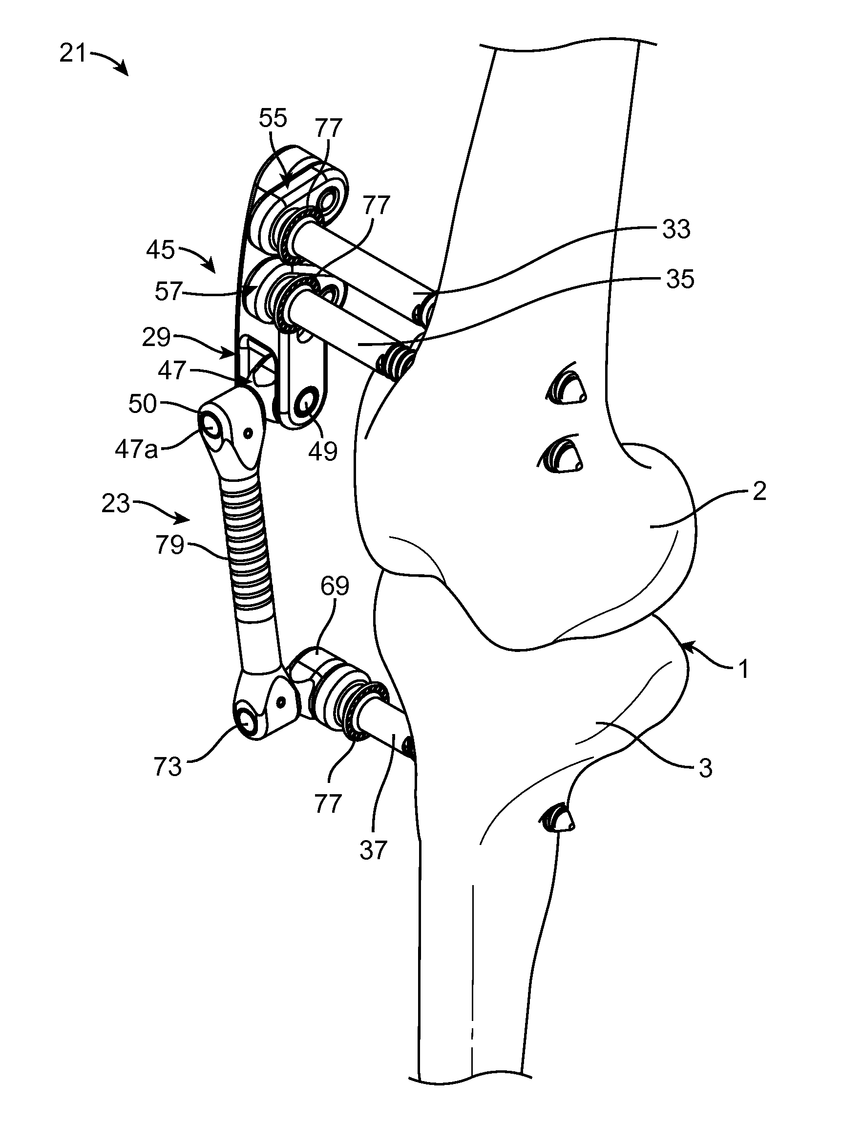
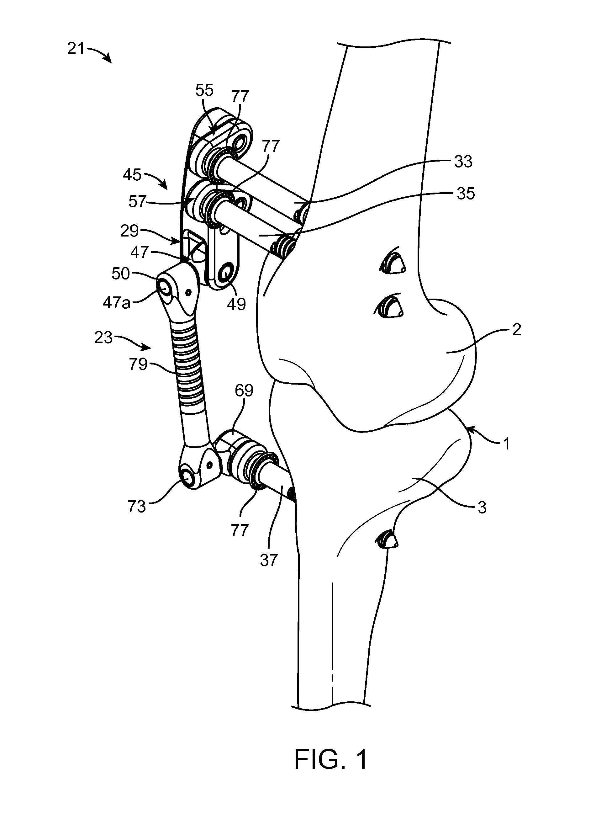
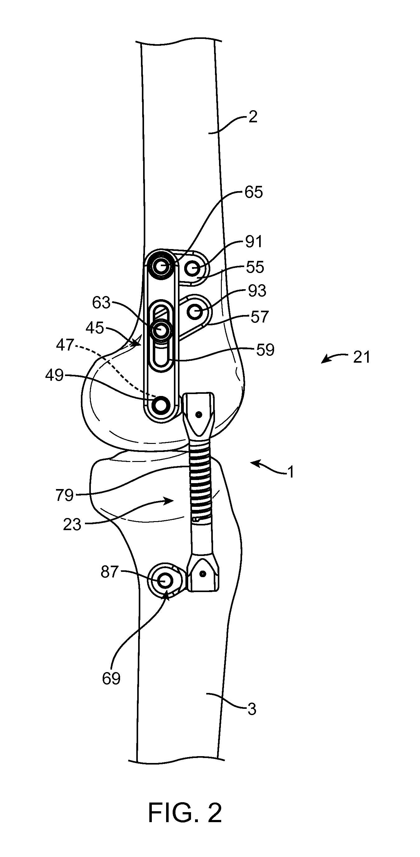
[0032]Referring now to the drawings, which are provided by way of example and not limitation, the disclosed embodiments are directed to apparatus and methods for treating the knee joint. However, these embodiments may also be used in treating other body joints, and to alleviate pain associated with the function of diseased or misaligned members forming a body joint while preserving range of motion of the joint. The embodiments described below relate to apparatuses and methods for reducing the amount of load carried by the natural joint anatomy.

[0033]Certain of the embodiments include joint unloading devices designed to minimize the loading of the anatomy of the body, such as that found at a body joint. It has been postulated that to minimize pain, unloading or load absorption of 1-40% of the forces on the joint, in varying degrees, may be necessary. Variable unloading or energy absorption in the range of 5-20% can be a target for certain applications.

[0034]It has also been found tha...


PUM


Abstract

Various methods for treating a joint are disclosed herein. According to one method, a joint is surgically treated by performing a surgical repair treatment on tissue within the joint capsule; implanting a load reducing device at the joint and entirely outside of the joint capsule to reduce load transmitted by the treated tissue to allow for the tissue within the joint capsule to heal; and partially unloading the joint during healing of the surgical repair site.

Description

CROSS REFERENCES TO RELATED APPLICATIONS[0001]This application claims the benefit of U.S. Application Ser. No. 61 / 504,886, filed Jul. 6, 2011, the entire disclosure of which is expressly incorporated herein.BACKGROUND AND SUMMARY[0002]The present invention relates to a joint unloading device and, more particularly, to a transcutaneous joint unloading device.[0003]Joint replacement is one of the most common and successful operations in modern orthopaedic surgery. It consists of replacing painful, arthritic, worn or diseased parts of a joint with artificial surfaces shaped in such a way as to allow joint movement. Osteoarthritis is a common diagnosis leading to joint replacement. Such procedures are a last resort treatment as they are highly invasive and require substantial periods of recovery. Total joint replacement, also known as total joint arthroplasty, is a procedure in which all articular surfaces at a joint are replaced. This contrasts with hemiarthroplasty (half arthroplasty)...

Claims


Application Information

Patent Timeline
Patent Type & Authority Applications(United States)
IPC IPC(8): A61F2/08
CPCA61B17/56A61B17/6425A61B17/683A61B2017/564A61B17/86A61B2017/567A61B17/80
Inventor LANDRY, MICHAEL E.CLIFFORD, ANTON G.MAKOWER, JOSHUA
Owner MOXIMED INC
Why Eureka
Try Eureka