
Electrical heating system for a section of fluid transport pipe, section and pipe equipped with such an electrical heating system

a technology of electric heating system and fluid transport pipe, which is applied in the direction of electric/magnetic/electromagnetic heating, pipe heating/cooling, transportation and packaging, etc., can solve the problems of deteriorating heating of the transport pipe, the difficulty of any maintenance or repair operation, and the hostile environment of land pipelines, so as to achieve the effect of improving robustness

Active Publication Date: 2013-01-17
ITP
View PDF2 Cites 21 Cited by
  • Summary
  • Abstract
  • Description
  • Claims
  • Application Information

AI Technical Summary

Benefits of technology

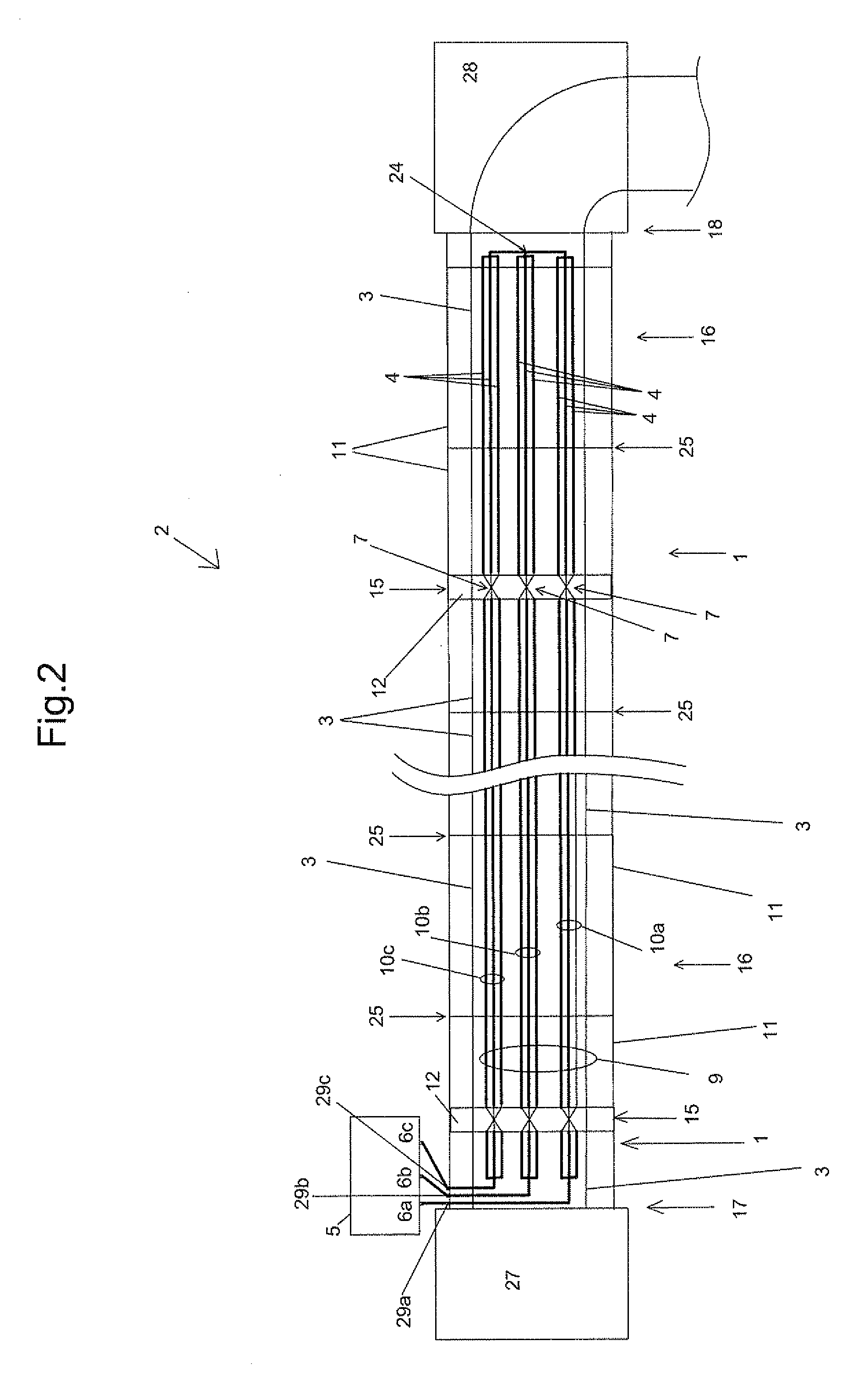
The present invention provides an improved electrical heating system for fluid transport pipes that overcomes the drawbacks of previous systems. The system includes a heating system for at least one section of a fluid transport pipe, which comprises electric wires arranged around the pipe and powered by a multi-phase power supply. The system also includes connecting units that connect the electric wires of different groups together, creating a heating circuit. The system can be used in a laying process for the pipe, where the sections are welded together and the electric wires are connected to a reinforcing ring. The technical effects of the invention include improved robustness against faults in the electrical connections, improved heating efficiency, and improved protection against pneumatic and mechanical damage.

Problems solved by technology

Subsea hydrocarbon transport pipelines may be installed at depths of up to several kilometers making them all the more difficult to access for any maintenance or repair operations.
These same difficulties may be encountered for land pipelines laid in a hostile environment.
One problem, however, arises in the case of a defective connection between two wires.
The heating of the transport pipe is thus deteriorated despite the fact that the electrical safety components allow the lines associated with the defective line to be deactivated.
This problem concerning the faults in the electrical connections can occur for any type of section assembled end to end to form a pipeline.
For straight sections that are typically 12 meters, 24 meters or 72 meters long, and which are assembled at sea on a pipe laying ship to gradually form the pipeline, the problem is all the greater in that it is impossible to act on the pipe after it has been installed on the sea bed.
It is further known that failures in electrical systems are in the majority linked to failures in the connections.
The multiplication of wires and sections to produce a long length pipe thus leads to systems containing several tens of thousands of connections, thereby elevating the overall risk to an unacceptably high level.

Method used


Image

  • Electrical heating system for a section of fluid transport pipe, section and pipe equipped with such an electrical heating system
  • Electrical heating system for a section of fluid transport pipe, section and pipe equipped with such an electrical heating system
  • Electrical heating system for a section of fluid transport pipe, section and pipe equipped with such an electrical heating system

Examples


Embodiment Construction

[0058]The invention will now be described in more detail.

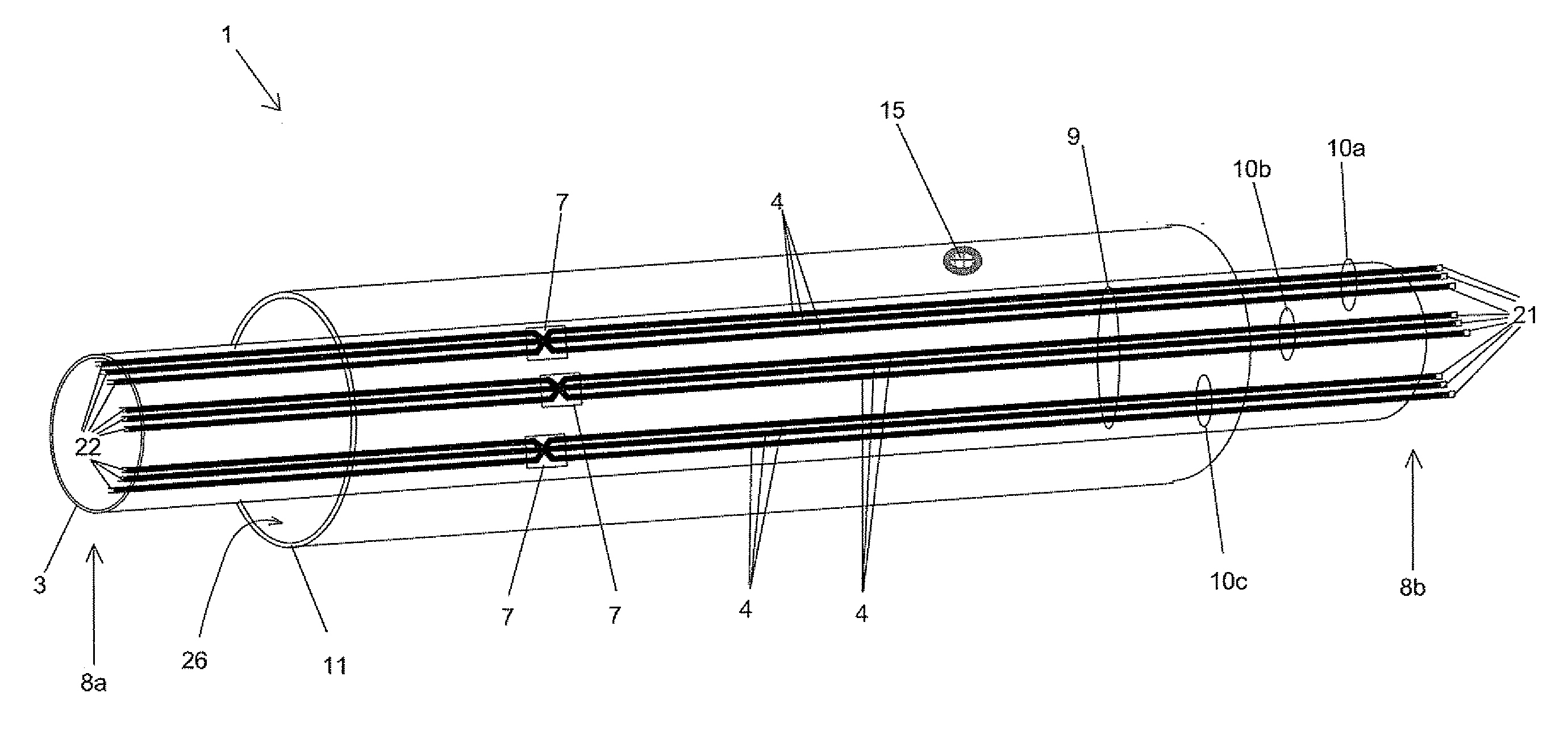
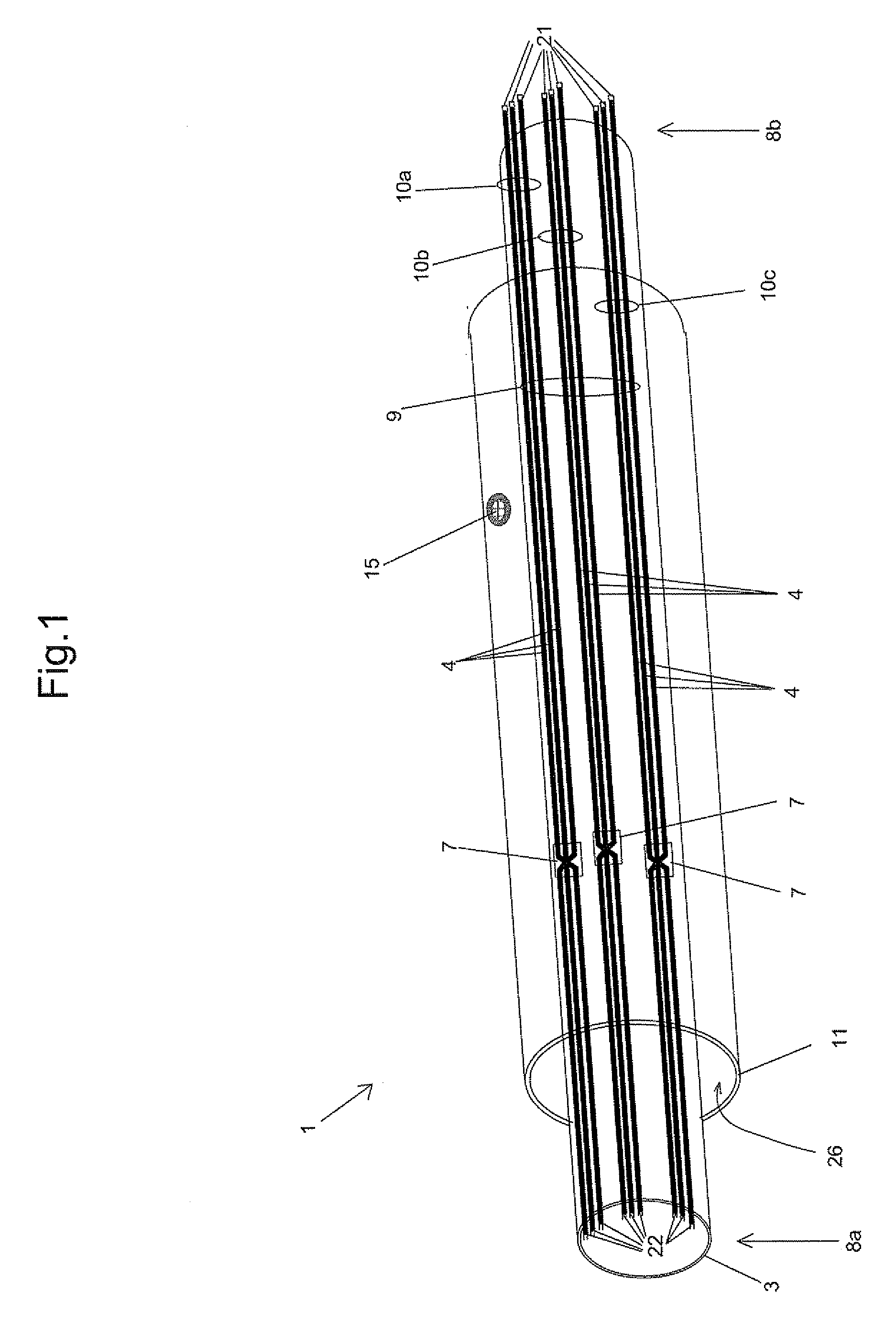
[0059]FIG. 1 shows a section 1 intended to be assembled with other sections to form a fluid transport metallic pipe 2 to transport fluids, such as hydrocarbons. The section 1 comprises a first casing 3, or inner casing, in which the fluid to be transported flows.

[0060]A second casing 11 is arranged around and at a distance from the first one 3. The two casings 3 and 11 delimit an annulus 26. This annulus 26 accommodates, for example, the heating system as well as thermal insulation for the first casing 3. The first casing 3 may be metallic, as may the second casing. The first and second casings are, for example, made of steel or another metal. The second casing 11 is shown transparently so as to reveal the heating system, no insulating material being shown in FIG. 1.

[0061]A pipe with a single casing may also be envisaged with electric heating wires pressed against the outer wall of the metallic casing and held in place by hold...


PUM

PropertyMeasurementUnit
Temperatureaaaaaaaaaa
Poweraaaaaaaaaa
Electrical conductoraaaaaaaaaa

Abstract

The invention relates to an electrical heating system for at least one section of a fluid transport pipe, the pipe comprising a casing in which the fluid to be transported flows, the heating system comprising electric wires arranged around the casing and intended to be powered, via connection elements, by an electrical power supply comprising several phases, system in which the electric wires are arranged in at least one set of several groups each comprising several electric wires, each of the groups in said set being intended to be supplied by a distinct phase, the electrical heating system comprising connecting units to perform an electrical connection and linking together the electric wires of each of said groups.

Description

BACKGROUND OF THE INVENTION[0001]1. Field of the Invention[0002]The technical scope of the present invention is that of heating system for fluid transport pipes. The invention relates in particular to the subsea or land transportation of hydrocarbons over great distances.[0003]2. Description of the Related Art[0004]To transport fluids in cold environments, for example for the subsea transport of hydrocarbons, one technical solution consists in heating the pipes to avoid the formation of obstructions resulting from the fluid cooling. A minimal temperature must therefore be maintained by heating the transport pipe. Electrical heating may be implemented to this end.[0005]The robustness of the heating equipment must be suited to the environmental conditions in which the transport pipe is to be placed. Subsea hydrocarbon transport pipelines may be installed at depths of up to several kilometers making them all the more difficult to access for any maintenance or repair operations. These s...

Claims


Application Information

Patent Timeline
IPC IPC(8): F16K49/00H01R43/00F16L53/34F16L53/38
CPCF16L53/004F16L53/008Y10T29/49117H05B2203/016F17D1/18H05B6/56H05B1/0244H05B3/42H05B6/06H05B6/108H05B2214/03F16L53/34F16L53/38Y10T137/6606F16L53/35F16L1/16F16L53/00H05B3/40
Inventor GEERTSEN, CHRISTIAN
Owner ITP
Learn More