Simplified Multilevel DC Converter Circuit Structure

a dc converter and circuit structure technology, applied in the direction of dc-ac conversion without reversal, power conversion systems, electrical equipment, etc., can solve the problems of affecting the overall efficiency of converting dc voltage to ac voltage, so as to improve the overall efficiency of converting dc voltag

Inactive Publication Date: 2013-01-17
NAT PENGHU UNIV
View PDF1 Cites 2 Cited by
  • Summary
  • Abstract
  • Description
  • Claims
  • Application Information

AI Technical Summary

Benefits of technology

[0006]Therefore, it is a primary objective of the present invention to overcome the aforementioned problem by providing a simplified multilevel DC converter circuit structure applied high-quality single-phase or three-phase AC electric applications such as the applications of driving a motor, an alternative energy generation system, an uninterruptible power supply, and an audio amplifier. These applications simply require a use of six power switches only, and thus the component cost can be reduced effectively. In addition, two of the power switches perform the switching operation at a low frequency (60 Hz), and thus the loss for switching the low-power switches ON or OFF can be reduced to improve the overall efficiency of converting DC voltage to AC voltage.

Problems solved by technology

However, the foregoing conventional DC converter circuit adopts eight power switches Sa1, Sa2, Sa3, Sa4, Sb1, Sb2, Sb3, Sb4, not only involving too many components, but also failing to lower the component cost effectively, since every power switch has to bear a withstand voltage equal to the supply voltage.
Furthermore, all power switches perform the switching operation at a high frequency when the conventional DC converter circuit converts direct currents, and thus incurring a higher switching loss and an easier damage to the power switches.

Method used


Image

  • Simplified Multilevel DC Converter Circuit Structure
  • Simplified Multilevel DC Converter Circuit Structure
  • Simplified Multilevel DC Converter Circuit Structure

Examples


Embodiment Construction

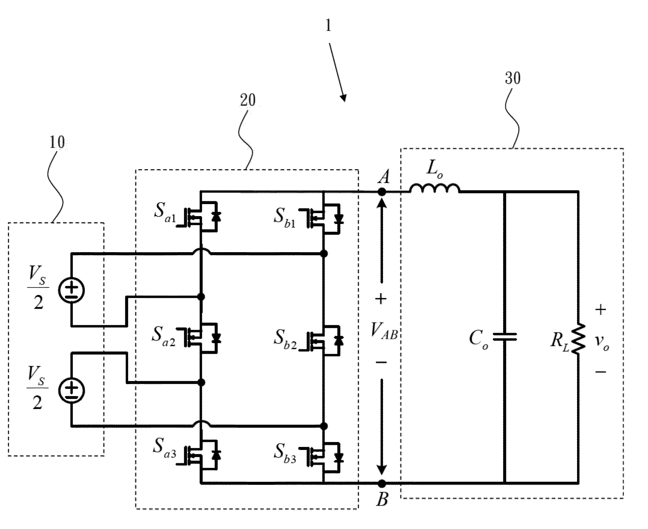
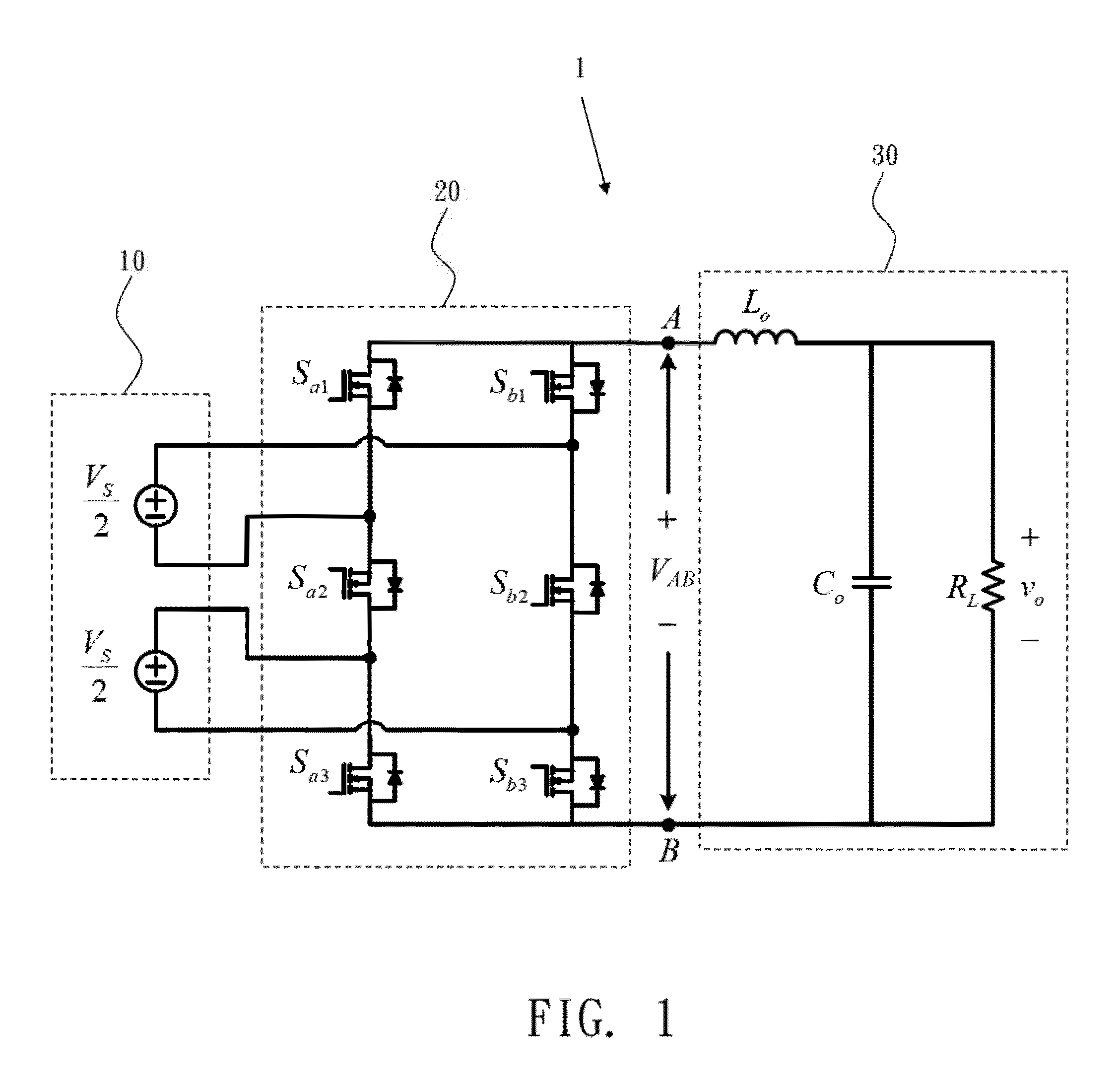
[0025]With reference to FIG. 1 for a schematic circuit diagram of a simplified multilevel DC converter circuit structure 1 of the present invention, the simplified multilevel DC converter circuit structure 1 comprises a dual input DC power supply 10, a power control module 20 and an AC side low-pass filter 30, wherein each of the dual input DC power supply 10 supplies half of the rated DC voltage to the power control module 20, and the power control module 20 is composed of six power switches Sa1, Sa2, Sa3, Sb1, Sb2, Sb3, and different switching combinations of the power switches Sa1, Sa2, Sa3, Sb1, Sb2, Sb3 can be controlled to convert an input of DC voltage into an output of AC voltage, and two of the power switches Sa2, Sb2 among the power control module 20 perform a low-frequency switching twice every cycle (60 Hz) of the output voltage, and the remaining power switches Sa1, Sa3, Sb1, Sb3 perform the switching at a high frequency, and the AC side low-pass filter 30 synthesizes t...


PUM


Abstract

A simplified multilevel DC converter circuit structure comprises a dual input DC power supply, a power control module and an AC side low-pass filter, wherein each of the dual input DC power supply supplies half of the rated DC voltage to the power control module, and the power control module is composed of six power switches, and different switching combinations of each power switch are controlled to convert a DC voltage to an output of an AC voltage, and two of the power switches of the power control module perform a low-frequency switching twice every cycle of the output voltage, and the withstand voltage is equal to the input voltage, and the remaining power switches perform the switching by a high frequency, and the withstand voltage is only half of the input voltage, such that a multilevel voltage can be outputted, and a low harmonic AC waveform can be outputted from the AC side low-pass filter.

Description

BACKGROUND OF THE INVENTION[0001](a) Field of the Invention[0002]The present invention relates to a DC converter circuit, in particular to a simplified multilevel DC converter circuit structure comprising six power switches.[0003](b) Description of the Related Art[0004]With reference to FIG. 15 for a conventional DC converter circuit, the DC converter circuit includes eight power switches Sa1, Sa2, Sa3, Sa4, Sb1, Sb2, Sb3, Sb4, wherein different switching combinations of the power switches are controlled to achieve the effect of converting a DC voltage to an AC voltage for the output.[0005]However, the foregoing conventional DC converter circuit adopts eight power switches Sa1, Sa2, Sa3, Sa4, Sb1, Sb2, Sb3, Sb4, not only involving too many components, but also failing to lower the component cost effectively, since every power switch has to bear a withstand voltage equal to the supply voltage. Furthermore, all power switches perform the switching operation at a high frequency when th...

Claims


Application Information

Patent Timeline
Patent Type & Authority Applications(United States)
IPC IPC(8): H02M7/537
CPCH02M7/483H02M7/48
Inventor LIAO, YI-HUNGLAI, CHING-MING
Owner NAT PENGHU UNIV
Why Eureka
Try Eureka