Thermally-assisted magnetic recording medium and magnetic recording/reproducing device using the same

a technology of magnetic recording medium and magnetic recording/reproducing device, which is applied in the field of magnetic recording medium, can solve the problems of thermal stability deterioration, disassembly of magnetization directions, and deterioration of thermal stability

Active Publication Date: 2013-01-17
TDK CORPARATION
View PDF5 Cites 27 Cited by
  • Summary
  • Abstract
  • Description
  • Claims
  • Application Information

AI Technical Summary

Problems solved by technology

However, thermal stability may be deteriorated when the volume V of the magnetic microparticles is excessively reduced, and therefore, magnetization directions may be disarranged because of the influence of temperature or the like.
When the volume of each magnetic microparticle is simply reduced to enhance the recording density, the thermal fluctuation index is lowered, the thermal stability is deteriorated, and therefore it becomes unable to perform the recording.
However, since the coercive force He of the magnetic microparticles becomes larger in proportion to the anisotropy energy constant Ku, a disadvantage occurs that it becomes unable to perform the recording with a conventional head.
However, the media disclosed in the respective above-described publications are not media having a most preferable lamination film configuration as a magnetic recording medium used for thermally-assisted recording.
With the mediums, spreading of a heating spot applied from a magnetic head for thermally-assisted recording to a film surface of the magnetic recording medium cannot be sufficiently suppressed so that an obstacle to achieve higher density recording may occur, and the magnetization direction of a perpendicularly written magnetization cannot be stabilized so that signal to noise ratio (SN) is deteriorated causing difficulties to achieve the higher recording density.

Method used


Image

  • Thermally-assisted magnetic recording medium and magnetic recording/reproducing device using the same
  • Thermally-assisted magnetic recording medium and magnetic recording/reproducing device using the same
  • Thermally-assisted magnetic recording medium and magnetic recording/reproducing device using the same

Examples


first embodiment

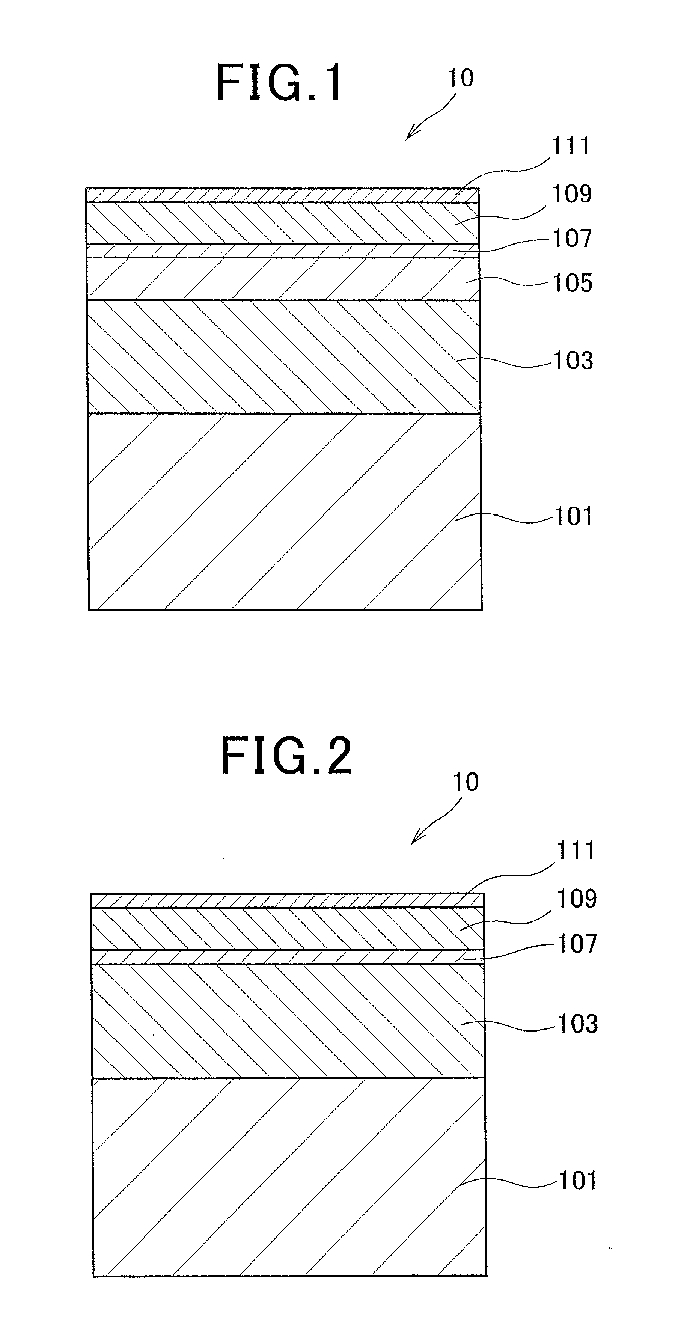
[0140]FIG. 1 is a cross-sectional view schematically illustrating a preferable configuration example of a first embodiment of a TAMR medium of the present invention. As illustrated in FIG. 1, a TAMR medium 10 of the present invention is configured with a lamination structure in which a soft under layer (SUL) 103, a thermal barrier layer 105, a magnetization direction arrangement layer 107, a magnetic recording layer 109, a protective layer 111 are laminated in this order on a substrate 101.

[0141](Description of Substrate 101)

[0142]For the substrate 101 of the present invention, glass, aluminum, silicon, plastic, or the like can be used. Also, a composite substrate can be used as well in which a metal, a ceramic, or the like is deposited on a substrate made of a hard material. A thickness of such substrate 101 is not limited in particular; however, the thickness is set to, for example, approximately 0.5-1.0 mm. As a configuration of the substrate 101, a configuration in a disk-shape ...

second embodiment

[0170]FIG. 2 is a cross-sectional view schematically illustrating a preferable configuration example of a second embodiment of the TAMR medium of the present invention. As illustrated in FIG. 2, a TAMR medium 10 of the second embodiment is configured with a lamination structure in which a SUL 103, a magnetization direction arrangement layer 107, a magnetic recording layer 109, and a protective layer 111 are laminated in this order on a substrate 101.

[0171]A different point of the TAMR medium 10 of the second embodiment illustrated in FIG. 2 from that of the first embodiment illustrated in the above-described FIG. 1 is that the thermal barrier layer 105 is eliminated and is not formed in the TAMR medium 10 of the second embodiment. Since the TAMR medium 10 of the second embodiment has the same configuration as the TAMR medium 10 of the above-described first embodiment other than the point, detailed description of each of the configuration layers herein is omitted.

[0172]Also in the TA...

third embodiment

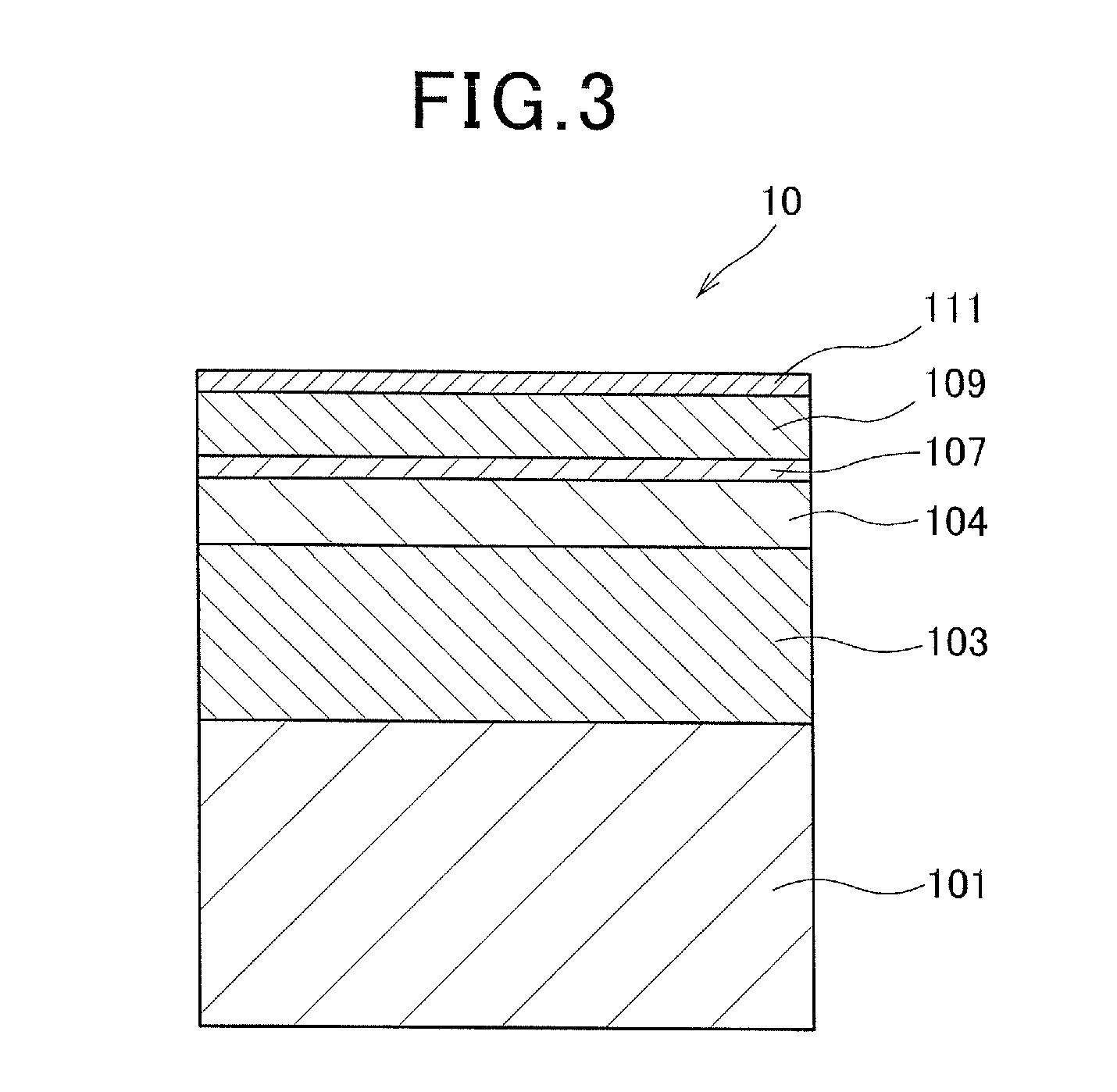
[0174]FIG. 3 is a cross-sectional view schematically illustrating a preferable configuration example of a third embodiment of the TAMR medium of the present invention. As illustrated in FIG. 3, a TAMR medium 10 of the third embodiment is configured with a lamination structure in which a SUL 103, a heat sink layer 104, a magnetization direction arrangement layer 107, a magnetic recording layer 109, and a protective layer 111 are laminated in this order on a substrate 101.

[0175]A different point of the TAMR medium 10 of the third embodiment illustrated in FIG. 3 from that of the first embodiment illustrated in the above-described FIG. 1 is that a heat sink layer 104 is formed as substitute for the thermal barrier layer 105. Other than the point, the TAMR medium 10 of the third embodiment has the same configuration as the TAMR medium 10 of the above-described first embodiment.

[0176]As a material used for the heat sink layer 104, a simple substance and an alloy, etc. of Cu, Ag, and Au c...


PUM

PropertyMeasurementUnit
thicknessaaaaaaaaaa
thicknessaaaaaaaaaa
thicknessaaaaaaaaaa

Abstract

A thermally-assisted magnetic recording (TAMR) medium of the present invention includes: a magnetization direction arrangement layer on a substrate; and a magnetic recording layer on the magnetization direction arrangement layer, wherein the magnetization direction arrangement layer is made of at least one selected from a group consisting of Co, Zr, CoZr, CoTaZr, CoFeTaZrCr, CoNbZr, CoNiZr, FeCoZrBCu, NiFe, FeCo, FeAlN, (FeCo)N, FeAlSi, and FeTaC so that a spreading of the heating spot applied from the magnetic head for thermally-assisted recording to the film surface of the magnetic recording medium is suppressed, and that an SN is improved by arranging the magnetization direction of the perpendicularly written recording magnetization to become identical to a perpendicular direction, and realizing the higher recording density.

Description

BACKGROUND[0001]1. Field of the Invention[0002]The present invention relates to a magnetic recording medium and particularly to a so-called thermally-assisted magnetic recording medium where information is recorded by applying an external magnetic field while local heating is performed to a portion of the medium. More specifically, the present invention relates to the thermally-assisted magnetic recording medium where information is recorded by applying the external magnetic field while the local heating is performed to reduce coercive force of a recording film by laser light irradiation, near-field light irradiation and the like, and also relates to a magnetic recording / reproducing device using the thermally-assisted magnetic recording medium.[0003]2. Description of the Prior Art[0004]In recent years, regarding magnetic recording / reproducing devices such as magnetic disk devices, etc., it has been required to improve the respective performances of a thin film magnetic head and a ma...

Claims


Application Information

Patent Timeline
Patent Type & Authority Applications(United States)
IPC IPC(8): G11B5/738G11B13/04
CPCG11B5/314G11B2005/0021G11B5/7325G11B5/7368G11B5/7369G11B5/7373G11B5/7375
Inventor TOMIKAWA, SATOSHIMIZUNO, TOMOHITO
Owner TDK CORPARATION
Why Eureka
Try Eureka