Storage Battery Cell, Assembled Battery, Assembled Battery Setup Method, Electrode Group, and Production Method of Electrode Group

a battery cell and battery technology, applied in the field of storage battery cells, can solve the problems of power density drop and power density drop of the battery cell as a whole, and achieve the effect of controlling the amount of heat emission by the battery cell without decreasing the energy density

Inactive Publication Date: 2013-01-17
HITACHI LTD
View PDF4 Cites 18 Cited by
  • Summary
  • Abstract
  • Description
  • Claims
  • Application Information

AI Technical Summary

Benefits of technology

[0029]According to the present invention, the amount of heat emission by the battery cells can be controlled without decreasing energy density.

Problems solved by technology

Since current does not flow in a portion where no electrode is formed, it may results in a decrease of power density.
However, the decreased amount of the active material causes a decrease in power density of a battery cell as a whole.

Method used


Image

  • Storage Battery Cell, Assembled Battery, Assembled Battery Setup Method, Electrode Group, and Production Method of Electrode Group
  • Storage Battery Cell, Assembled Battery, Assembled Battery Setup Method, Electrode Group, and Production Method of Electrode Group
  • Storage Battery Cell, Assembled Battery, Assembled Battery Setup Method, Electrode Group, and Production Method of Electrode Group

Examples


first embodiment

[0047]According to the first embodiment, the storage battery cell of the present invention is applied to a lithium ion secondary battery cell. Hereafter, the lithium ion secondary battery cell according to the first embodiment is explained with reference to FIGS. 1 to 3.

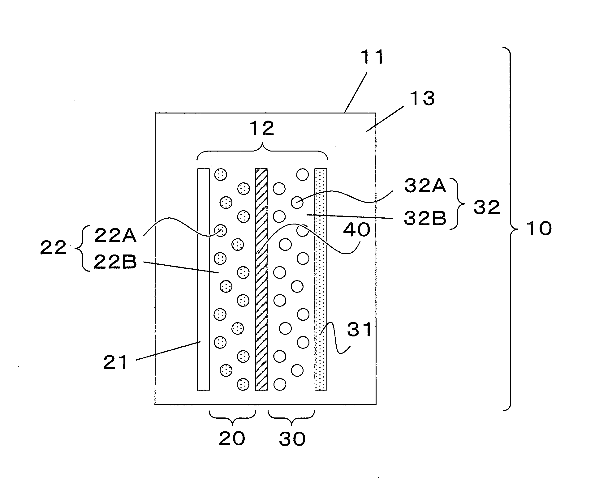
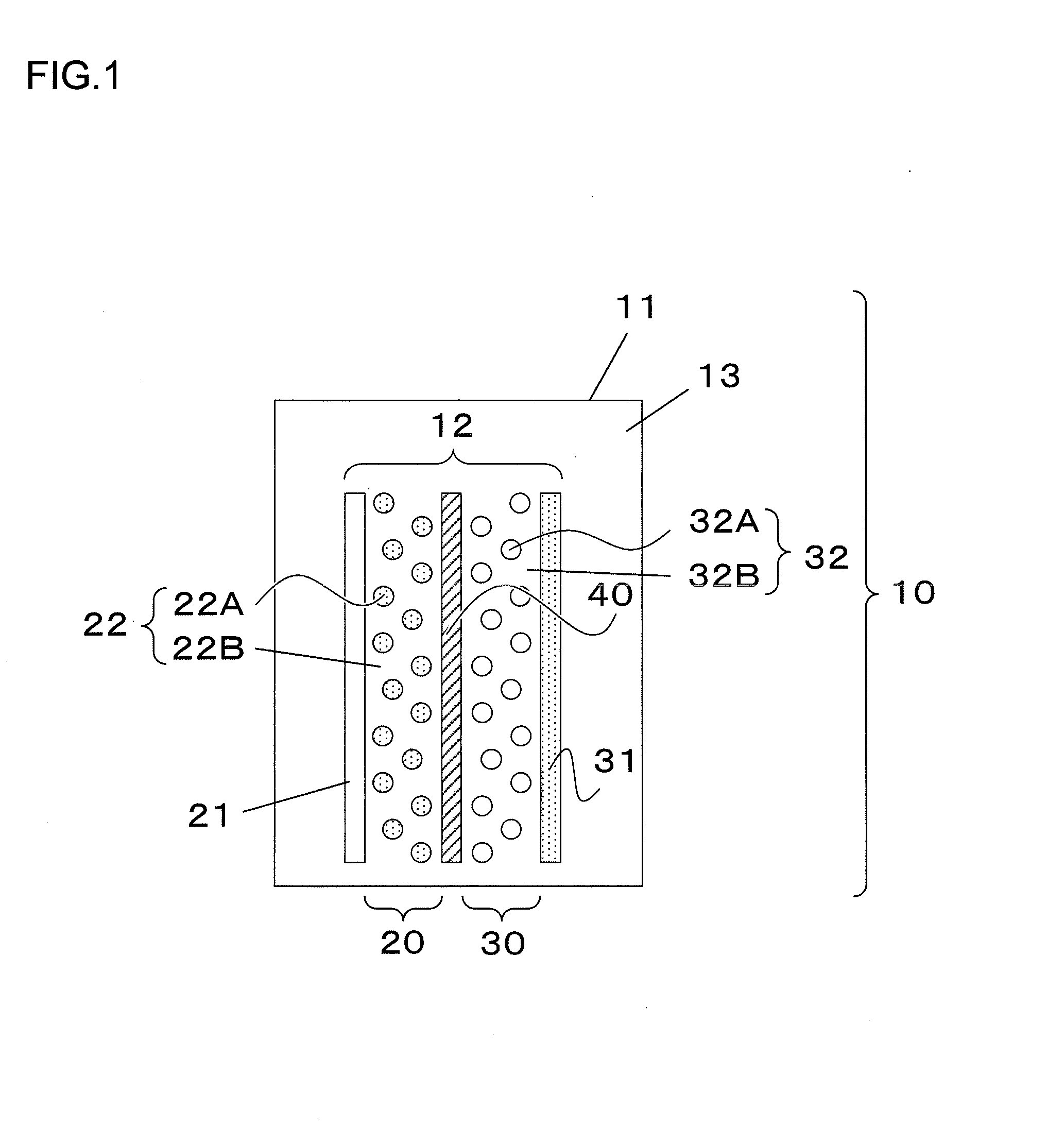
[0048]FIG. 1 presents a schematic diagram showing a lithium ion secondary battery cell 10 according to the first embodiment. The lithium ion secondary battery cell 10 includes as main constituent elements a battery cell container 1, a laminated-type electrode group 12, and an electrolyte 13 injected in the battery cell container 11 in which the laminated-type electrode group 12 are housed.

[0049]The laminated-type electrode group 12 are constituted by a sheet-like positive electrode 20 and a sheet-like negative electrode 30, which are laminated together with a separator 40 that intervenes between the electrodes. The positive electrode 20 is constituted by a positive current collector foil 21, which is a positive elect...

second embodiment

[0071]The storage battery cell according to a second embodiment of the present invention is explained with reference to FIGS. 5 and 6. In the figures, parts that are the same as or corresponding to parts of the first embodiment are assigned with numerals in the 100s and explanation is made concentrating on differences between the first and second embodiments. According to the second embodiment, the present invention is applied to a cylindrical wound-type storage battery cell. The electrode group used in this embodiment is in the form of an elongate sheet similar to the electrode group shown in FIG. 4 except that the thickness of the electrode layer is gradually increased or decreased along the longitudinal direction instead of the width direction.

[0072]In FIGS. 5 and 6, a cylindrical wound-type storage battery cell 10A is constituted by housing a laminated-type electrode group 112 that is wound around a winding core (not shown) in a container 111 and injecting an electrolyte 113 in ...

third embodiment

[0083]A storage battery cell according to a third embodiment of the present invention is explained with reference to FIGS. 7 and 8. It is to be noted that in the figures, parts that are the same as or corresponding to parts of the first embodiment are assigned with numerals in the 200s and explanation is made concentrating on differences between the first and second embodiments.

[0084]According to the third embodiment, the present invention is applied to a laminated-type storage battery cell provided with tabs that are used as external terminals, in which a positive electrode tab and a negative electrode tab are provided on one end of the battery cell.

[0085]In FIGS. 7 and 8, a laminated-type storage battery cell with tabs 10B includes a plate-like container 211, which houses therein a laminated-type electrode group 212 fabricated by laminating a positive electrode 220, a negative electrode 230 and a separator 240 that intervenes between the electrodes. A positive electrode tab 401 co...


PUM

PropertyMeasurementUnit
thicknessesaaaaaaaaaa
thicknessaaaaaaaaaa

Abstract

A storage battery cell includes: an electrode group in which a positive electrode including positive electrode current collector foil provided with a positive electrode layer containing a positive electrode active material, a negative electrode including negative electrode current collector foil provided with a negative electrode layer containing a negative electrode active material, and a separator that intervenes between the positive electrode and the negative electrode are laminated; a battery cell container; and an electrolyte, wherein: the positive electrode active material and the negative electrode active material respectively are substantially uniformly distributed, and the positive electrode layer and the negative electrode layer are provided respectively with regions in which respective quotients of the positive active material and the negative active material in the electrolyte are varied.

Description

INCORPORATION BY REFERENCE[0001]The disclosure of the following priority application is herein incorporated by reference: Japanese Patent Application No. 2011-152989 filed on Jul. 11, 2011.BACKGROUND OF THE INVENTION[0002]1. Field of the Invention[0003]The present invention relates to a technology in the field of storage battery cell such as lithium ion secondary battery cell.[0004]2. Description of Related Art[0005]In recent years, it has been demanded to promote energy saving accounted for national movement for saving resources such as fossil fuels and for preventing global warming. Under the circumstances, among secondary battery cells, a lithium ion battery cell with a large capacity and a small size is expected as an important electric storage device for realizing an energy saving society. To this end, demand is being expanded centered on consumer applications for power sources for mobile information terminals and cordless electric devices, industrial applications such as power...

Claims


Application Information

Patent Timeline
Patent Type & Authority Applications(United States)
IPC IPC(8): H01M2/02H01M4/139H01M4/64H01M4/00H01M2/10H01M50/213H01M50/463
CPCH01M2/105Y10T29/49115H01M2/1673H01M2/18H01M4/13H01M10/04H01M10/052H01M10/058H01M10/0585H01M10/0587H01M10/5008H01M10/5016H01M6/42H01M6/44H01M10/5093H01M2004/021Y02E60/122H01M2/1077H01M10/625H01M10/66H01M10/617Y02E60/10Y02P70/50H01M50/213H01M50/46H01M50/463H01M50/54H01M50/403H01M50/105
Inventor WATANABE, ERIKATOGASHI, SHIGENORI
Owner HITACHI LTD
Why Eureka
Try Eureka