Transmission gear box for bikes

a technology for transmission gearboxes and bikes, applied in mechanical equipment, transportation and packaging, gearboxes, etc., can solve the problems of increased driving energy of the driving mechanism, large shock of the transmission shift, and difficulty in running, so as to improve the structure of the transmission mechanism, minimize impact, and softly perform the transmission mode shifting process

Inactive Publication Date: 2013-01-17
SONG YUN YI
View PDF4 Cites 5 Cited by
  • Summary
  • Abstract
  • Description
  • Claims
  • Application Information

AI Technical Summary

Benefits of technology

[0020]A transmission gear box for bikes according to the present invention improves structure of a transmission mechanism that is applied to a speed conversion device of each bike, to thus minimize impact on a transmission gear box that may occur during clutching transmission gears through manipulation of shifting a transmission mode and selecting a transmission mode gearshift regardless of speed of pedals.
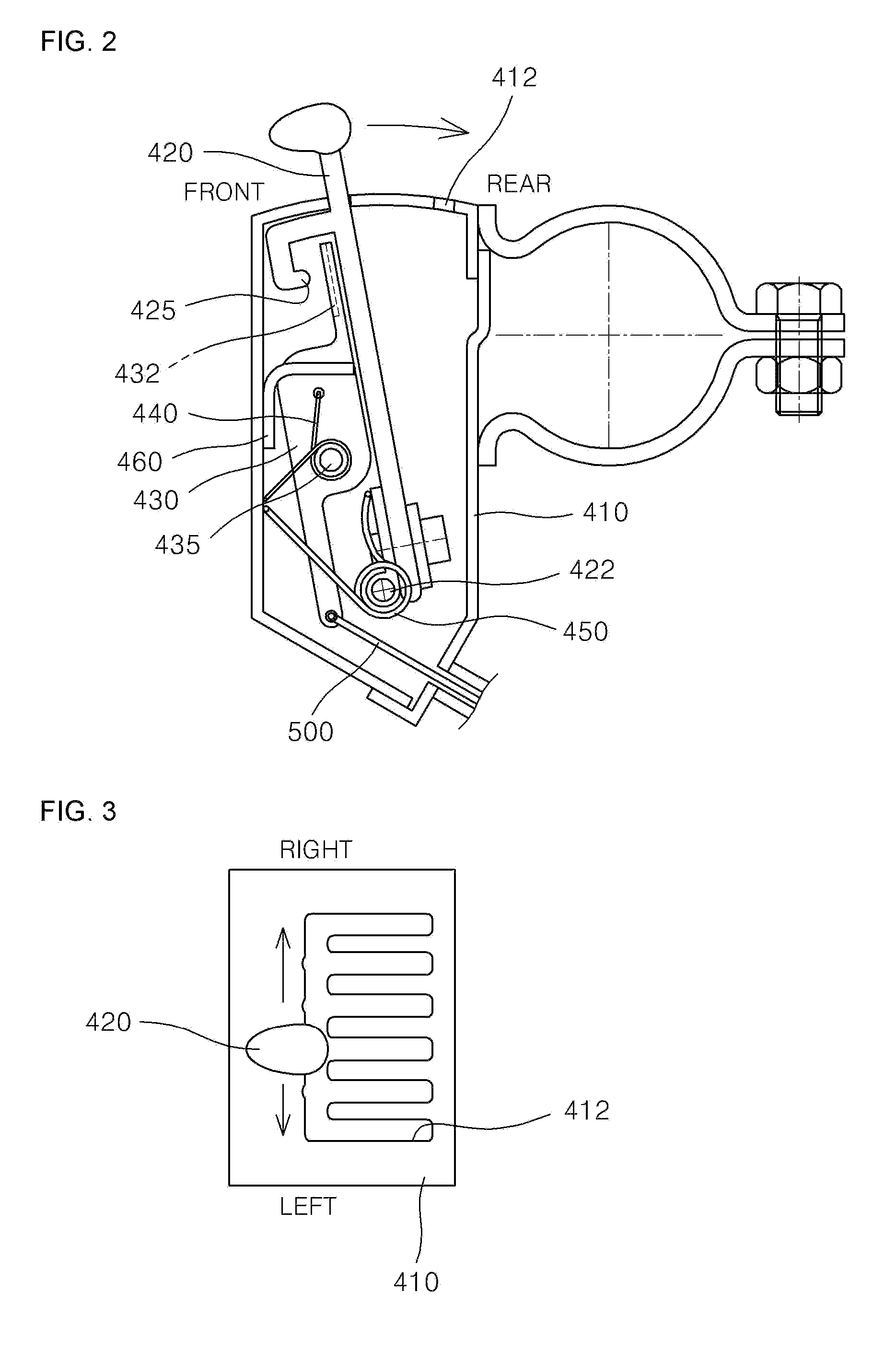
[0021]According to the present invention, a cable that is selected during manipulation of shifting a transmission mode of a transmission lever of a bike and a ring gear that is selected through the medium of a clutching unit are fixed by transmission gear engagement, to thus softly perform a transmission mode shifting process and to thereby minimize a transmission mode shift shock.
[0022]Further, according to the present invention, since it is possible to select user's desired transmission mode gearshift regardless of speed of pedals, the transmission gear box for bikes may immediately respond to user's desired transmission ratio even at departure after stop, to thereby provide a useful effect of improving responsiveness at the time of shifting a transmission mode.

Problems solved by technology

In particular, such a driving mechanism needs more driving energy in upward climbing roads.
Accordingly, the existing speed conversion device for use in bikes has a disadvantage that it is difficult to run unless the transmission gear box is shifted to a low speed transmission mode in the case that each bike stops at a high speed transmission mode and then starts to run again.
In addition, the existing speed conversion device for use in bikes has a drawback that a transmission mode shift shock is caused during shifting transmission modes in a transmission gear box, in particular, the transmission shift shock becomes large during performing a high speed transmission mode shifting process.

Method used


Image

  • Transmission gear box for bikes
  • Transmission gear box for bikes
  • Transmission gear box for bikes

Examples


Embodiment Construction

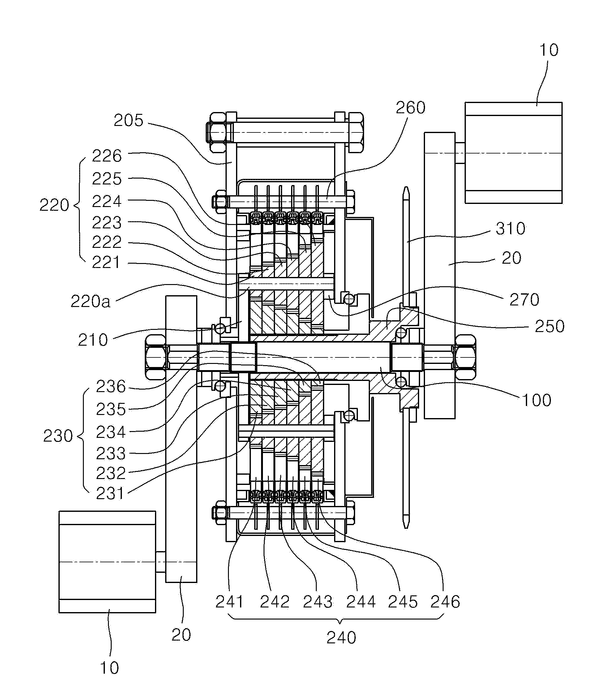
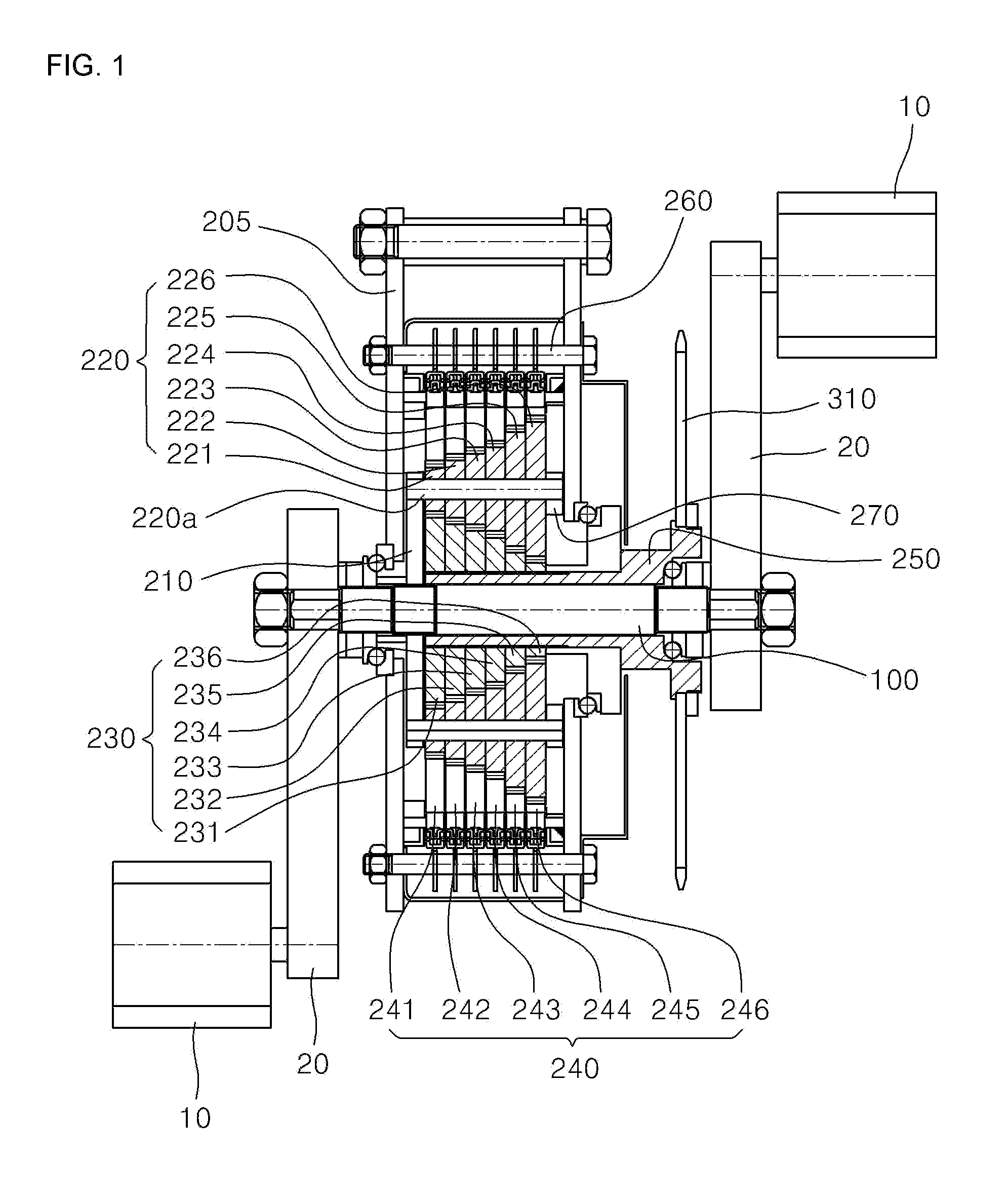
[0047]Hereinbelow, a transmission gear box for use in bikes according to preferred embodiments of the present invention will be described with reference to the accompanying drawings.

[0048]In recent years, a speed conversion device that is provided in the inside of a rear wheel hub for use in a bike is being developed and used, other than a general speed conversion device having gears of several diameters around axes of front and rear wheels and a chain transmitting power between the gears, to thus convert speed by changing position of the chain. In the case of the speed conversion device that is provided in the inside of a rear wheel hub, small gears are arranged in a hub shell to thus convert speed at a gear tooth ratio.

[0049]A transmission mode shifting mechanism of the speed conversion device suffers from a transmission shifting impact during performing a transmission mode shifting operation, and causes a trouble that transmission mode gearshifts should be manipulated appropriate...


PUM


Abstract

Provided is a transmission gear box for bikes including: crank arms that receive a rotational driving force from rotatable pedals of each bike and transmits the received rotational driving force to a main shaft; a transmission gear unit that receives the rotational driving force from the main shaft and performs a transmission mode shifting operation at a gear tooth ratio according to a selected transmission mode gearshift; a lever manipulation unit that selects one of the transmission mode gearshifts of the transmission gear unit according to manipulation of a transmission mode shift lever, to thus manipulate one of cables connected to the respective transmission mode gearshifts; and a clutching unit that is operated by one cable selected by the lever manipulation unit to thus make one of ring gears of the transmission gear unit fixed in a gear tooth engagement coupling manner and to thereby manipulate a transmission mode shifting process of the transmission gear unit.

Description

BACKGROUND OF THE INVENTION[0001]The present invention relates to a transmission gearbox for bikes, and more particularly, to a transmission gear box whose structure is improved for use in bikes, thus freely shifting transmission modes regardless of the speed of pedals and minimizing a transmission shift shock during shifting the transmission modes.[0002]In general, in the case of existing bikes, a crankshaft distance between a pedal shaft and a pedal is fixed to be constant so that a driveability is determined and provided by only a driving force of pedals combined with the crankshaft.[0003]The driving mechanism that is a structure of determining the driveability for such existing bikes is done within a radius of rotation with a constant rotational torque of the pedal from the pedal shaft. In particular, such a driving mechanism needs more driving energy in upward climbing roads.[0004]In order to improve the above-described conventional defect, it is the most widely generalized to ...

Claims


Application Information

Patent Timeline
Patent Type & Authority Applications(United States)
IPC IPC(8): F16H3/44
CPCF16H3/66F16H2200/0052F16H2200/2092F16H2200/2046B62M11/145F16H2200/2017
Inventor SONG, YUN YI
Owner SONG YUN YI
Why Eureka
Try Eureka