
Real-time photovoltaic power plant control system

a photovoltaic power plant and control system technology, applied in non-electric variable control, process and machine control, instruments, etc., can solve the problems of insufficient simple inverter level voltage and power factor regulation, plant lack of centralized control system,

Inactive Publication Date: 2013-01-17
FIRST SOLAR INC (US)
View PDF17 Cites 48 Cited by
  • Summary
  • Abstract
  • Description
  • Claims
  • Application Information

AI Technical Summary

Benefits of technology

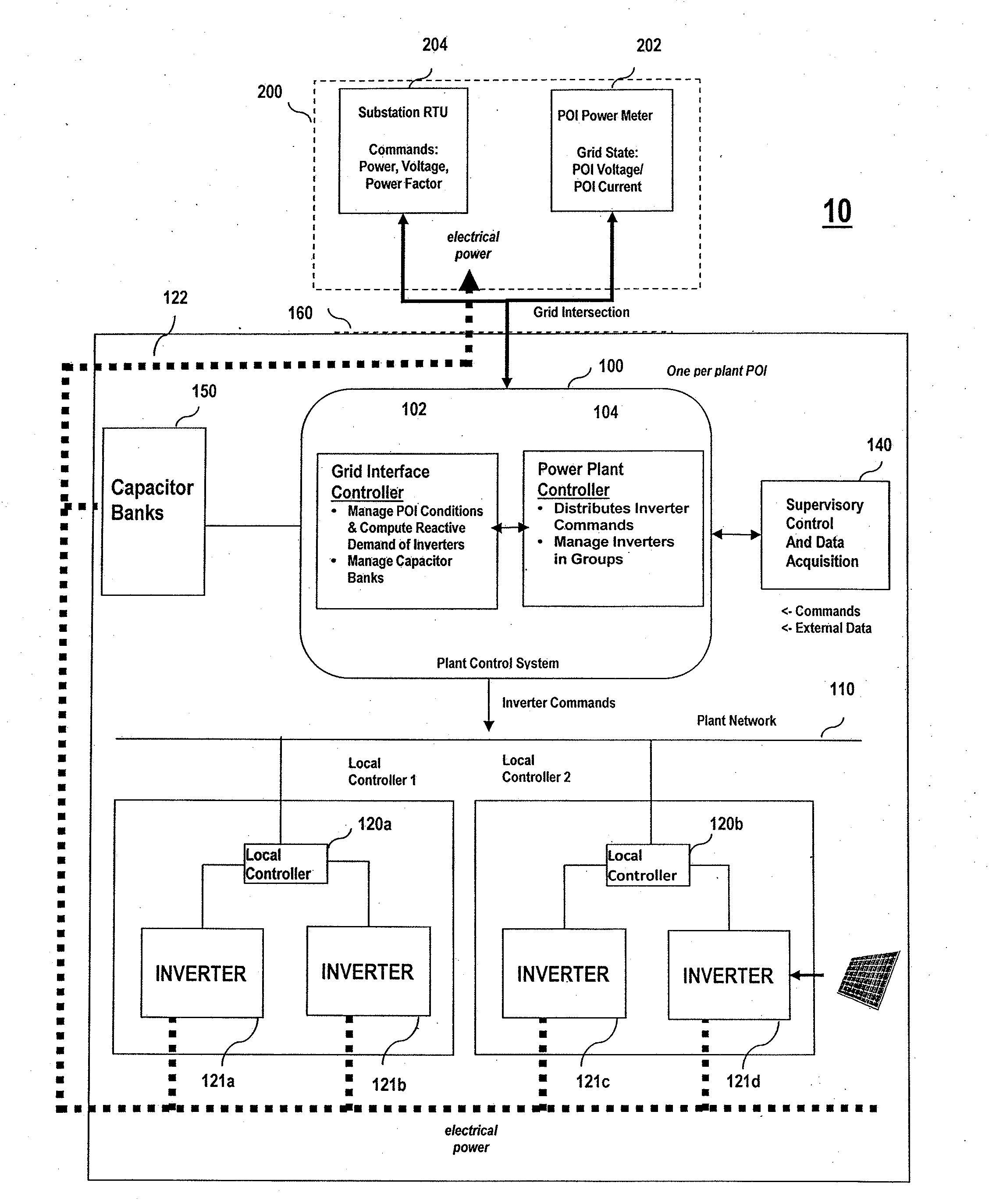
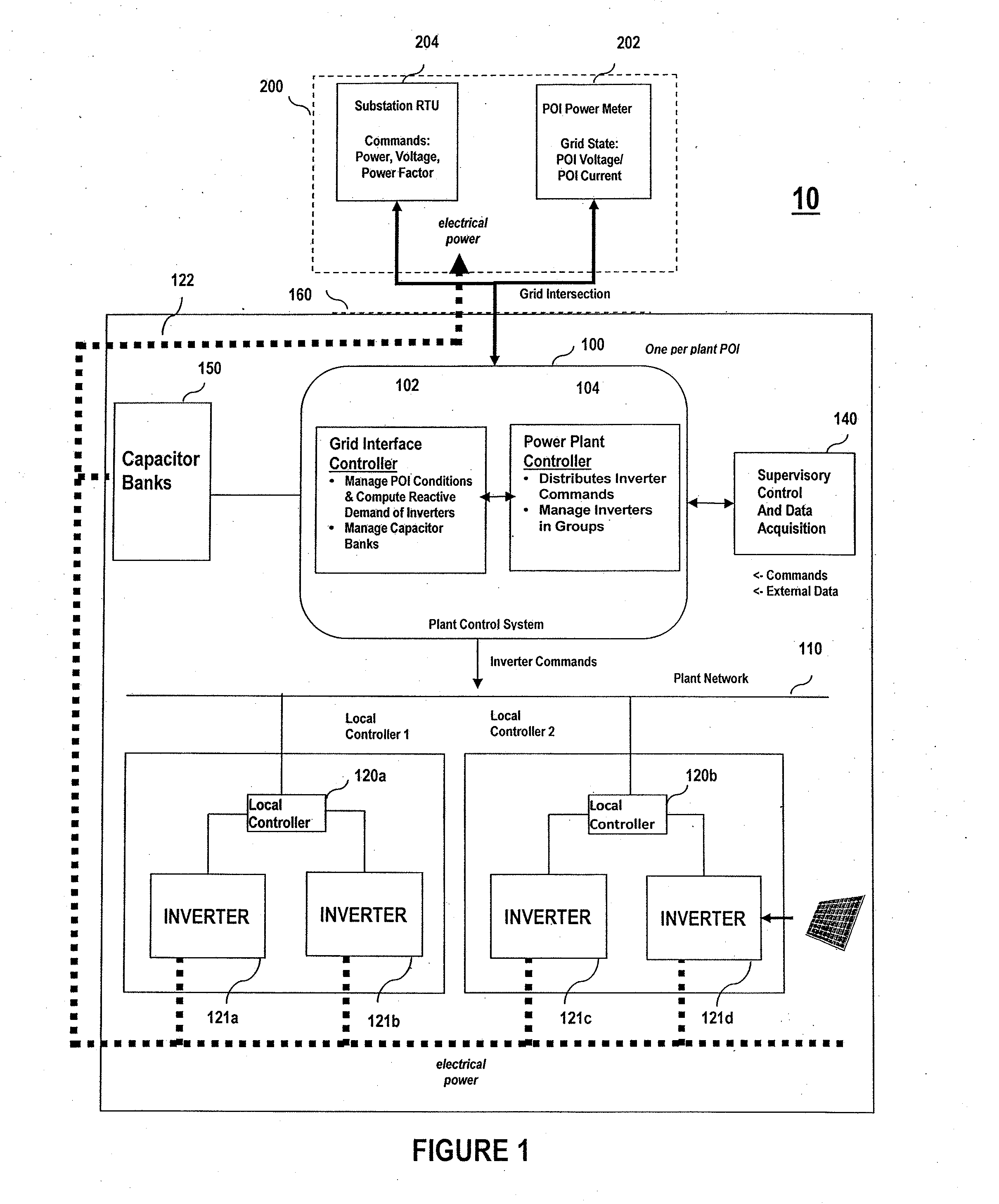
The invention is a real-time control system for photovoltaic power plants that can manage the output of multiple inverters in a way that ensures the plant operates as a single entity and meets the requirements of the electric grid. The system is capable of regulating voltage and power factor, as well as lowering real power output if needed. It can also adapt to different types of inverters and can communicate with other devices in the plant using a network. The technical effects of the invention include improved control of photovoltaic power plants, better performance and reliability, and better integration with the grid.

Problems solved by technology

Until now, the inverters provide the local control for power factor and / or voltage regulation and the plants lack a centralized control system that is capable of providing dynamic voltage or power factor regulation at the plants point of common coupling or point of intersection to the electric grid.
As the utility scale plants continue to increase both in size and population, simple inverter level voltage and power factor regulation is no longer sufficient.
In addition, the utility scale plants are not always populated with same-type or same-operating characteristic inverters, generally all from a single manufacturer, the systems must be capable to operate with different equipment supplied by different manufacturers.

Method used


Image

  • Real-time photovoltaic power plant control system
  • Real-time photovoltaic power plant control system
  • Real-time photovoltaic power plant control system

Examples


Embodiment Construction

[0012]In the following detailed description, reference is made to the accompanying drawings which form a part hereof, and which illustrate specific embodiments of the invention. These embodiments are described in sufficient detail to enable those of ordinary skill in the art to make and use them. It is also understood that structural, logical, or procedural changes may be made to the specific embodiments disclosed herein without departing from the spirit or scope of the invention.

[0013]Described herein is a real-time photovoltaic power plant control system adapted for use with utility scale plants. The system controls in real-time the output of connected inverters in a manner so that the plant performs as a single entity and required conditions at a point of grid intersection can be met. In one embodiment, the control system comprises a power plant controller, an associated grid interface controller which command operation of the power plant controller, and a plurality of local cont...


PUM


Abstract

A real-time photovoltaic power plant control system and method of control for plant output, voltage regulation and / or power factor regulation. The system comprises a grid interface controller configured to receive power information from a power grid and provide commands for controlling at least one active or reactive power supplied to the power grid, a power plant controller configured to receive commands from the grid interface controller for and direct real-time output of the power plant, a plurality of local controllers connected to and controlled by the power plant controller, and a plurality of inverters each connected to supply power from at least one photovoltaic device to the power grid and arranged such that each local controller is connected to and controls at least one inverter, the inverters reporting status information in real-time back to the local controllers, and the local controller reporting status information in real-time back to the power plant controller.

Description

FIELD OF THE INVENTION[0001]Embodiments of the invention relate to photovoltaic power plant control systems; specifically real-time control systems that manage utility scale photovoltaic plants.BACKGROUND OF THE INVENTION[0002]A utility scale photovoltaic plant contains tens to hundreds of independently operating inverters that convert photovoltaic-generated DC energy into AC for feeding the electric grid. Until now, the inverters provide the local control for power factor and / or voltage regulation and the plants lack a centralized control system that is capable of providing dynamic voltage or power factor regulation at the plants point of common coupling or point of intersection to the electric grid.[0003]As the utility scale plants continue to increase both in size and population, simple inverter level voltage and power factor regulation is no longer sufficient. More sophisticated photovoltaic plant control systems are needed that provide centralized voltage and power factor regul...

Claims


Application Information

Patent Timeline
IPC IPC(8): G06F1/26
CPCH02J3/383H02J13/0013Y02E10/563Y04S10/123Y02E40/72Y02E60/7807Y04S10/30Y02E60/74Y04S40/12H02J13/00002H02J2300/24H02J3/381H02J13/00006H02J13/00034Y02E10/56Y02E40/70Y02E60/00H02J3/48H02J3/46H02J3/50
Inventor CHEE, SIMONBELLACICCO, JOHNSAWYER, HARRYMORJARIA, MAHESH
Owner FIRST SOLAR INC (US)
Learn More