
Method and apparatus for separation of carbon dioxide from an off-gas from a fossil-fueled power station

Active Publication Date: 2013-01-24
SIEMENS ENERGY GLOBAL GMBH & CO KG
View PDF3 Cites 5 Cited by
  • Summary
  • Abstract
  • Description
  • Claims
  • Application Information

AI Technical Summary

Benefits of technology

This patent describes a separation apparatus for carbon dioxide that can be used in a fossil-fueled power station. The apparatus is designed to be energy efficient and quickly return to service in case of a standby mode. The patent also describes a process for separating carbon dioxide from a power station that allows for efficient standby mode and fast return to service, reducing the required energy demand.

Problems solved by technology

A great disadvantage of the absorption-desorption method above all is that for desorption a great deal of energy generally has to be expended.
This energy as a rule is extracted in the form of heating steam from the power station process, which significantly impairs the overall efficiency of the power station.
A big problem, furthermore, is that the described absorption-desorption process above all is very slow-acting on account of the necessary constructional size of the absorption-desorption column.
With the power station shut down, there is no longer the development of carbon dioxide-containing flue gas.
However, steam or heating steam is no longer available either.
If the carbon dioxide separation apparatus is shut down together with the power station without additional measures, a series of problems can occur.
As a result of settling particles or suspended particles, which are contained within the solvent, there is an increased risk of blocking.
Shutting down a carbon dioxide separation apparatus which is integrated into a power station also proves to be difficult.
Until reaching the operating temperature, a comparatively long time elapses in which no carbon dioxide can be separated or an economical degree of separation is not achieved.
The largely complete desorption of the solvent for a short downtime, however, on the one hand is uneconomical, and, moreover, is associated with a long restarting time of the desorption column Therefore, the carbon dioxide separation apparatus is preferably kept in standby mode in the case of a short downtime.

Method used


Image

  • Method and apparatus for separation of carbon dioxide from an off-gas from a fossil-fueled power station
  • Method and apparatus for separation of carbon dioxide from an off-gas from a fossil-fueled power station
  • Method and apparatus for separation of carbon dioxide from an off-gas from a fossil-fueled power station

Examples


Embodiment Construction

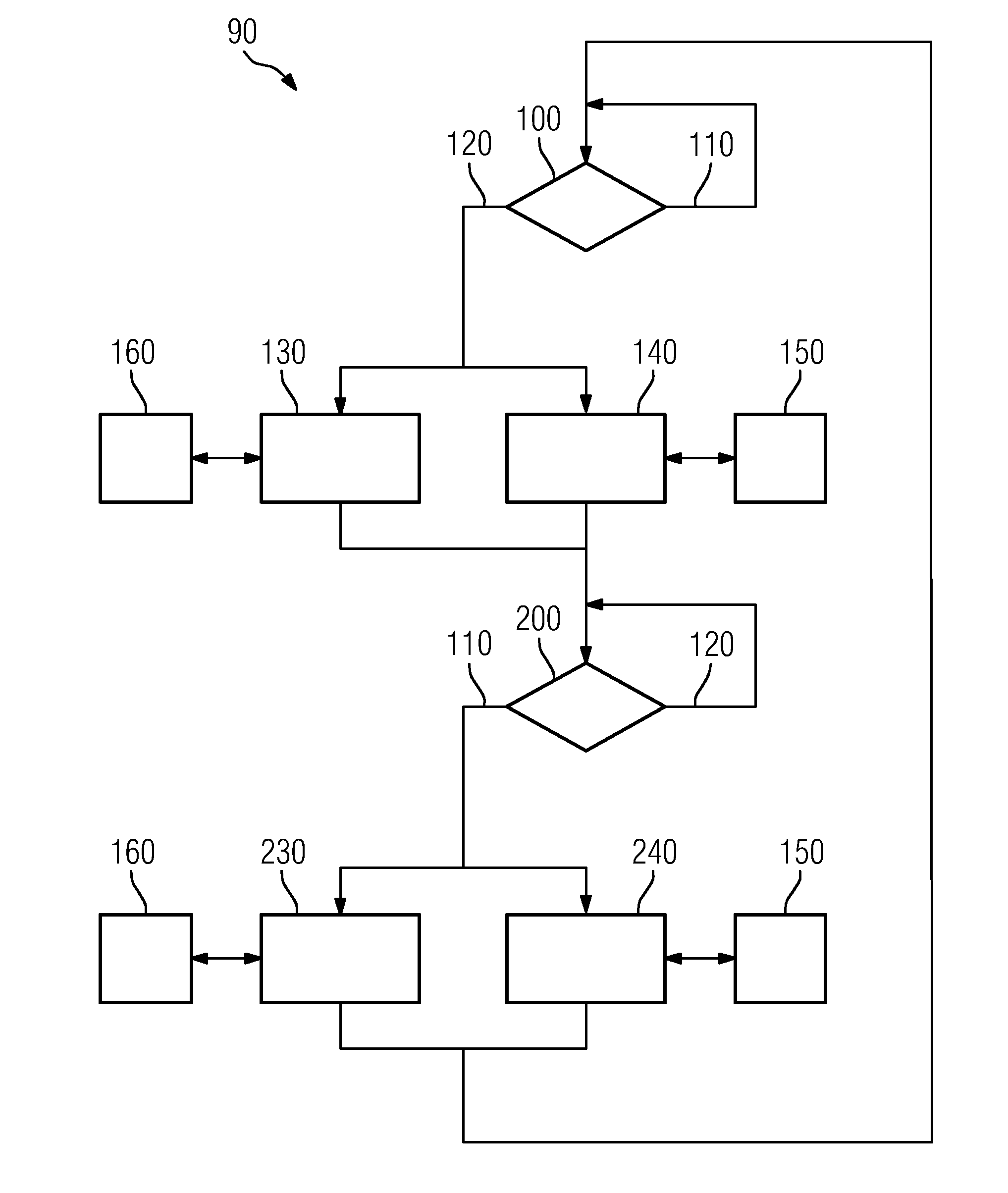
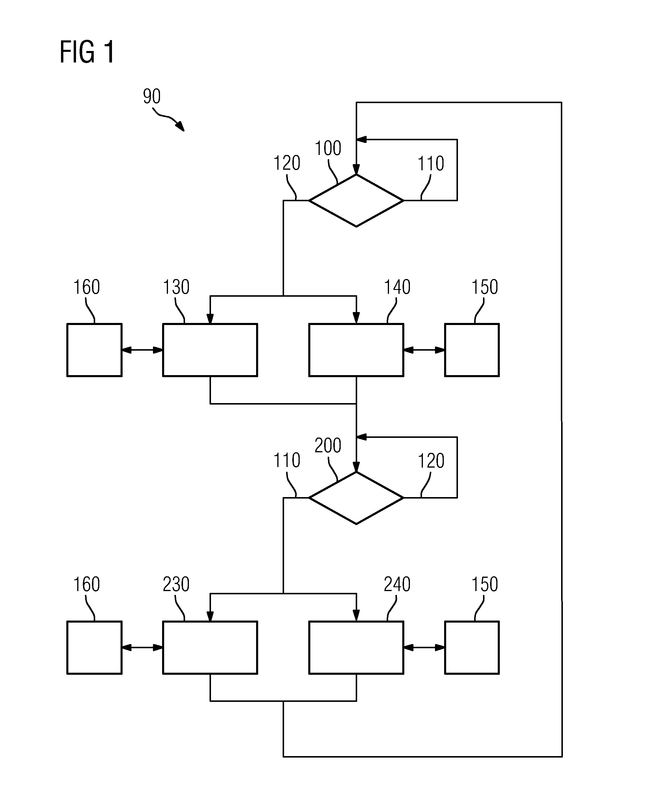
[0044]In FIG. 1, a carbon dioxide separation process 90 is shown. The process begins with the decision step 100. By the decision step 100, it is established whether the carbon dioxide separation process 90 is to be changed from the normal operating state 110 into the special operating state 120. If the special operating state 120 is established, the following processes are carried out:

[0045]Opening a first bypass 130

[0046]Opening a second bypass 140

[0047]The sequence of the processes which are to be carried out can vary. By opening the first bypass 130, regenerated solvent from the desorption process 160 is at least partially fed back again into the desorption process 160. By opening the second bypass 140, a laden solvent from the absorption process 150 is at least partially fed back into the absorption process 150. A further process step, in which from the regenerated solvent of the desorption process 160 heat is emitted to the laden solvent of the absorption process 150, is not sh...


PUM

PropertyMeasurementUnit
Temperatureaaaaaaaaaa

Abstract

A separation apparatus for carbon dioxide is provided which includes an absorption unit for absorbing flue gas from a fossil-fueled power station, a desorption unit and a heat exchanger which on the primary feed side is connected via an inlet-side feedback line to the desorption unit, and on the discharge side is connected via an outlet-side feedback line to the absorption unit. On the secondary feed side, the heat exchanger is connected via an inlet-side feed line to the absorption unit, and on the discharge side is connected via an outlet-side feed line to the desorption unit. A first bypass line connects the inlet-side feedback line to the outlet-side feed line so that a mostly closed first circuit with the desorption unit is formed, and a second bypass line connects the inlet-side feed line to the outlet-side feedback line so a mostly closed second circuit with the absorption unit is formed.

Description

CROSS REFERENCE TO RELATED APPLICATIONS[0001]This application is the US National Stage of International Application No. PCT / EP2011 / 053175, filed Mar. 3, 2011 and claims the benefit thereof. The International Application claims the benefits of German application No. 10 2010 013 729.4 DE filed Mar. 31, 2010. All of the applications are incorporated by reference herein in their entirety.FIELD OF INVENTION[0002]The invention refers to a separation apparatus for carbon dioxide for operation in a fossil-fueled power station, to a fossil-fueled power station with a separation apparatus for carbon dioxide, to a carbon dioxide separation process for a fossil-fueled station process, and to the use of a carbon dioxide separation process in a fossil-fueled power station.BACKGROUND OF INVENTION[0003]In fossil-fueled power stations for generating electric energy, a carbon dioxide-containing off-gas is produced as a result of combusting a fossil fuel. This carbon dioxide-containing off-gas as a ru...

Claims


Application Information

Patent Timeline
IPC IPC(8): B01D53/14F01K23/06F01K13/00C01B32/50
CPCB01D53/1425B01D53/1475B01D2257/504F23J15/006Y02E20/16F23J2219/60Y02C10/06Y02C10/04F23J2215/50Y02C20/40Y02E20/32B01D53/62F23J15/04
Inventor ROST, MIKESCHNEIDER, RUEDIGERSCHRAMM, HENNING
Owner SIEMENS ENERGY GLOBAL GMBH & CO KG
Learn More