
Optical fiber terminus assembly

Active Publication Date: 2006-08-03
MOLEX INC
View PDF18 Cites 13 Cited by
  • Summary
  • Abstract
  • Description
  • Claims
  • Application Information

AI Technical Summary

Benefits of technology

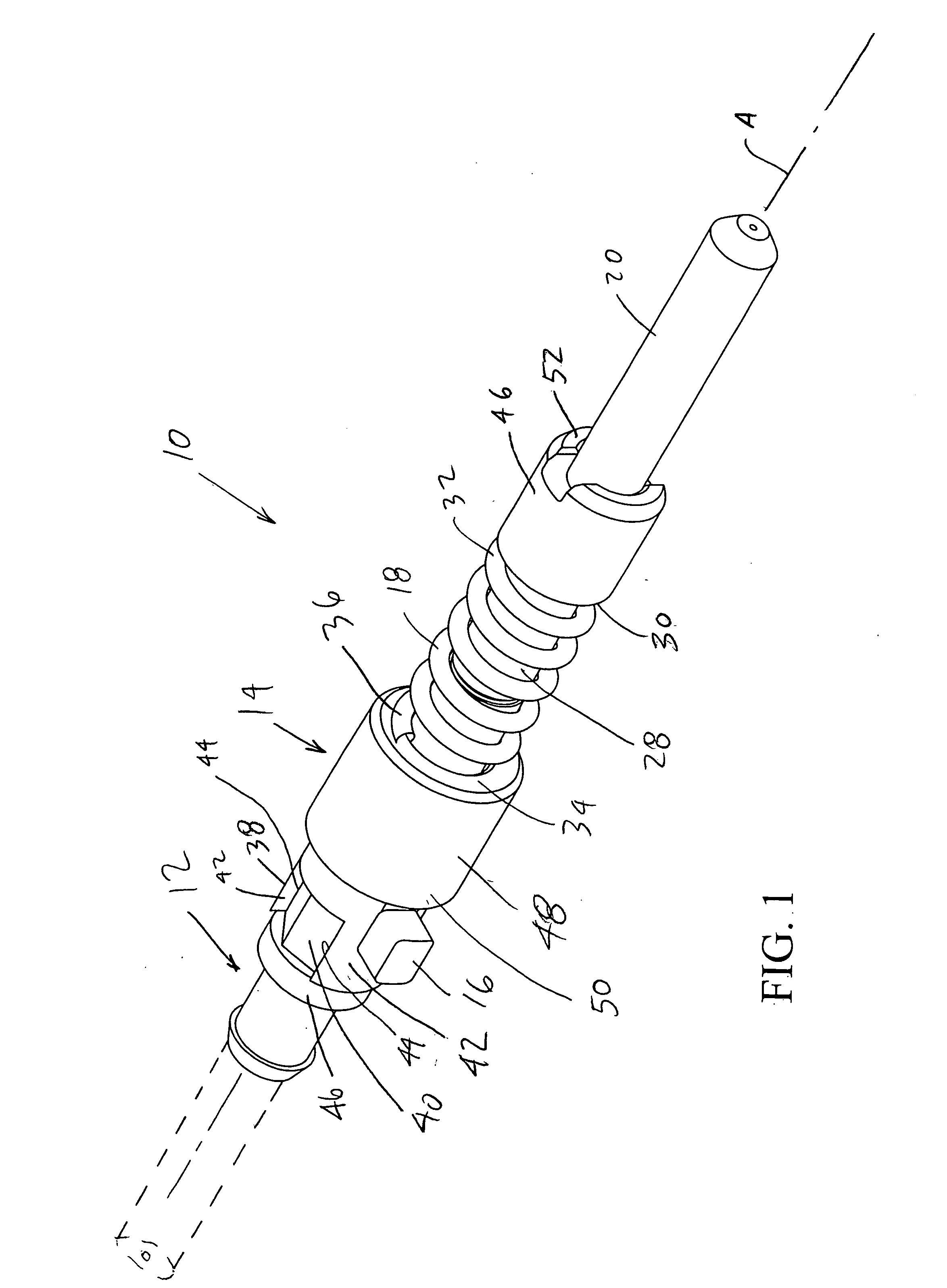
[0009] It is an object of the present invention to provide a terminus retention system that removes complexity from the connector system and enables users to quickly service connectors, yet retain the tuning of a terminus. As such, a connector is disclosed for terminating an optical fiber including a fiber holding structure for maintaining eccentricity compensation and having an end face in which an associated fiber is terminated within the holding structure and including an axial passageway which terminates in the end face and which is adapted to receive an end portion of the associated optical fiber. A connector housing has internal surfaces that define a cavity to accept the fiber-holding structure and includes first and second openings extending into the cavity and being positioned at opposite ends of the housing. The first opening is configured to receive an optical fiber and the second opening is configured to enable the end face of the holding structure to protrude through the opening. A latch is provided integral to the fiber holding structure to secure the fiber holding structure within an associated cavity. To preclude unintended decoupling therebetween, the latch includes a protrusion positioned on one or more surfaces of a sliding collar integral to the fiber holding structure. The latch is configured to engage the cavity structure by having the protrusion sweep an arc beneath an upper surface of the cavity. When the latch protrusion is swept through the arc, it is held beneath the rear face of the cavity by spring pressure created by compression of a primarily helical spring coaxially located along the fiber holding structure longitudinal axis.
[0012] The cylindrical plug of the present invention includes a tube whose outer cylinder surface has a circular cross section and whose axial passageway is substantially concentric with the outer cylinder surface and wherein the tube is made from ceramic or metallic materials. The fiber-holding structure is adapted to be held within the housing in a singular stable angular position such that the angular position of the fiber-holding structure with respect to the housing is constant. In addition, the fiber-holding structure sliding collar index key allows the entire fiber-holding structure to be removed from the connector housing yet maintain its singular stable angular position when returned to the connector housing. The connector housing includes first and second interconnecting housing members which each include an internal cavity for receiving the fiber-carrying structure. The second interconnecting member is generally cylindrical in shape so as to mate with the first interconnecting member. The first and second interconnecting members combine to form a structure that substantially encloses the fiber-holding structure. The first and second interconnecting members are made from a metallic, plastic or ceramic material and are secured together using a positive locking device such as a threaded collar, a coupling screw or external physical clamp.

Problems solved by technology

This is a particularly challenging task because the light-carrying region or core of an optical fiber is quite small.
As one might expect, it is presently impossible to make a perfect connection.
Manufacturing tolerances may approach “zero” but practical considerations such as cost, and the fact that slight misalignment is tolerable, suggest that perfection is unnecessary although stability across the operating environment of the fiber joint is critical.
Historically, due to manufacturing costs and design features, optical termini have tended to be manufactured as an assembly of loose components.
This is an undesirable effect as the housing becomes an integral element in tuning and if the terminus is removed from the housing (such as for cleaning or replacement), the tuning is in effect lost.
However, when consideration is taken of single mode optical fiber with an optical waveguide of only 8-9 microns in diameter, it can be seen how optical insertion loss can be dramatically impacted if control of the placement of the optical core is not maintained.
Once removed it is not possible to determine the exact positional relationship between the fiber holding structure and the connector body.
Existing optical termini systems are typically utilized in military connector systems and some designs incorporate anti-rotation features but none include an operative retention system and tuning capability as an integral part of the terminus.

Method used


Image

  • Optical fiber terminus assembly
  • Optical fiber terminus assembly
  • Optical fiber terminus assembly

Examples


Embodiment Construction

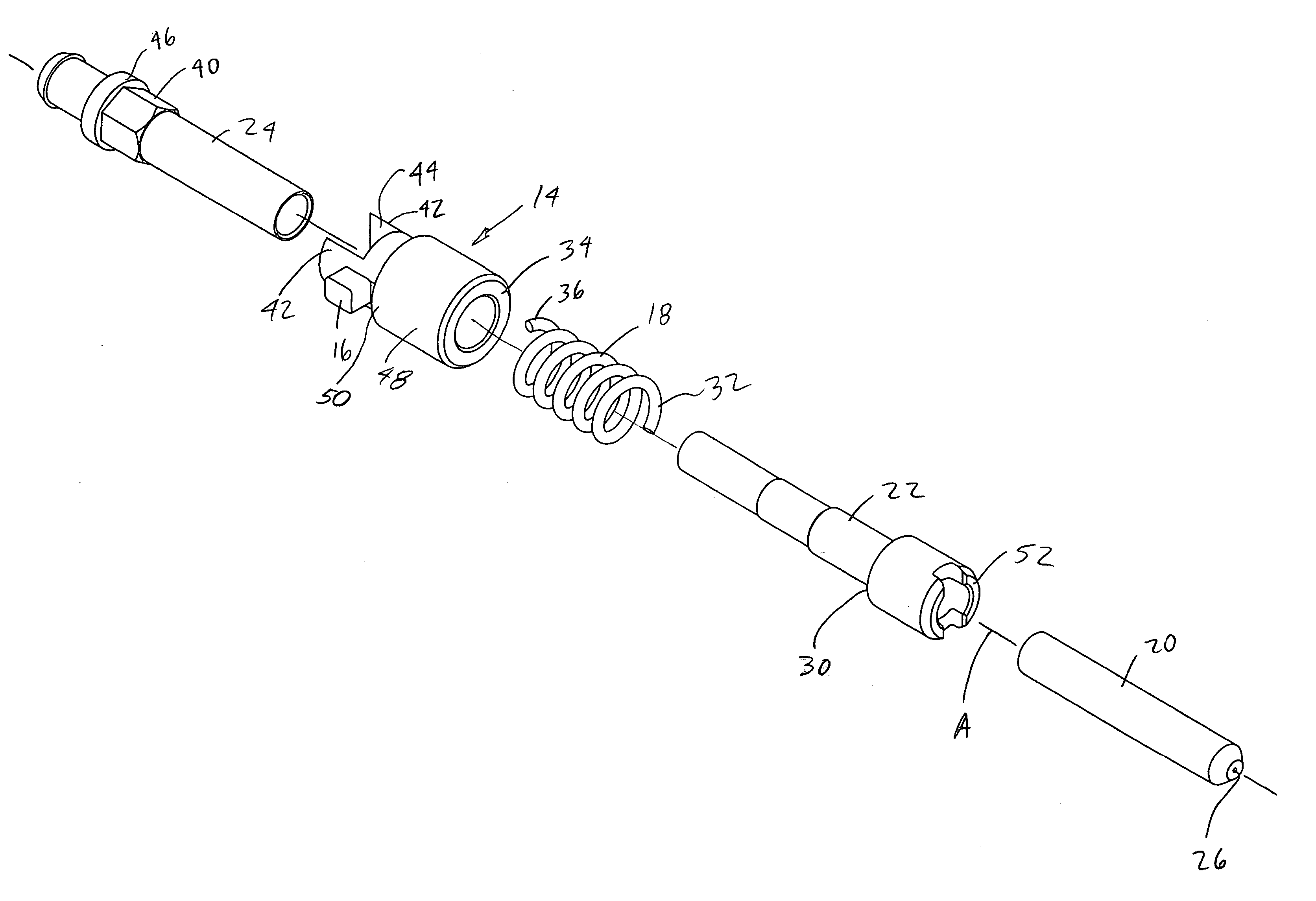
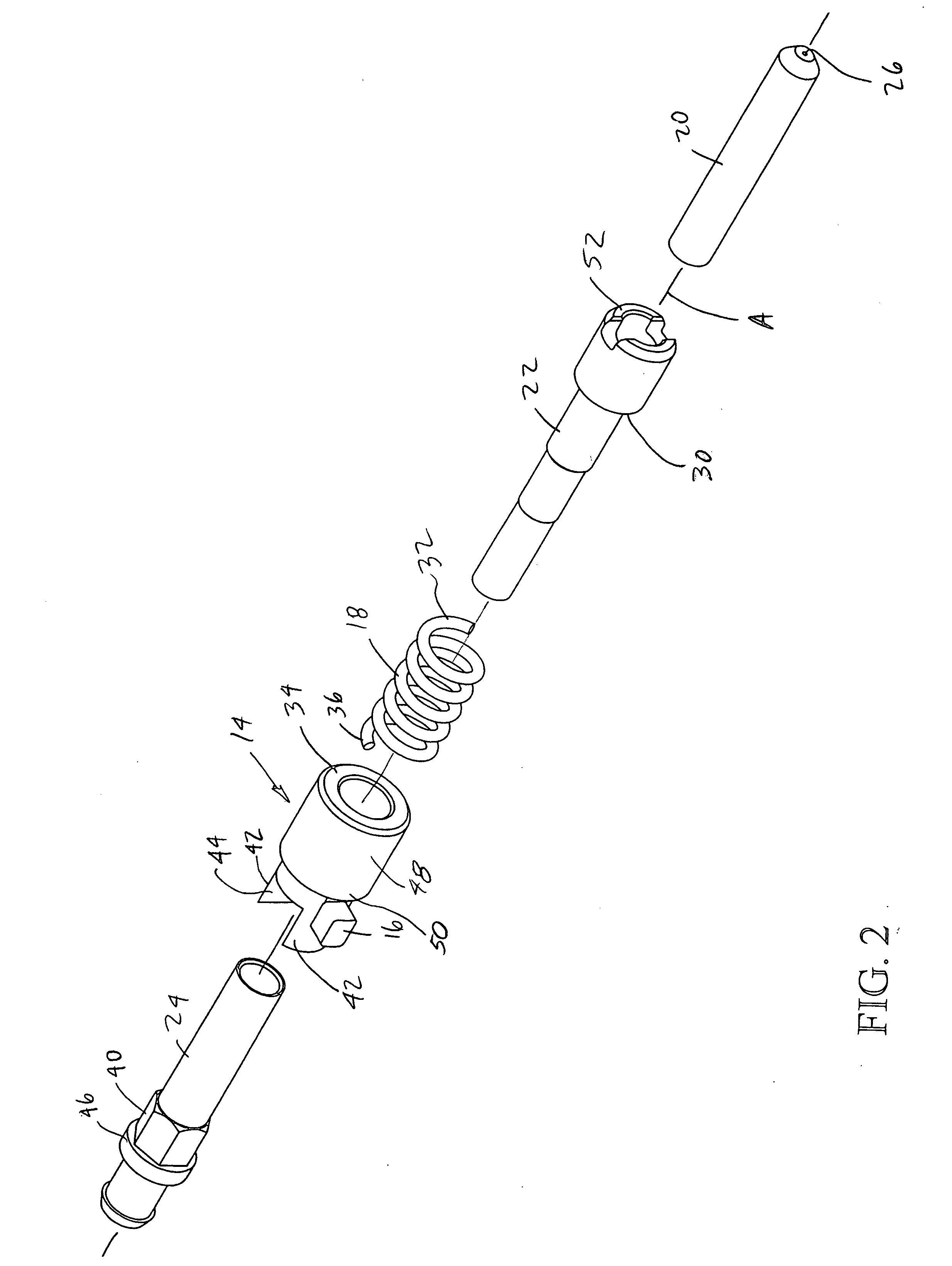
[0021] In accordance with one embodiment of the present invention and referring first to FIG. 1, an optical fiber support assembly or terminus 10 and an optical fiber connector that includes such terminus, as well as a method of assembly, are disclosed. The terminus includes three main components, inner main body or member 12, a sliding collar or outer member 14 with protrusion boss or tab 16 extending radially therefrom and substantially helical spring or biasing member 18. The inner main body is typically an assembly of three components (FIG. 2) a ferrule 20 (typically made of ceramic or metal), a forward section or body 22 that is joined to the ferrule with an adhesive or by a press-fit and a rear section or body 24 that is assembled with forward section 22 and captures the sliding collar and helical spring 18 therebetween. As described in more detail below, sliding collar 16 is indexable through the interaction between registration structure integral to the collar and indexing s...


PUM


Abstract

An optical fiber terminus includes an elongated body with a passage along a central axis for receiving a portion of an optical fiber cable therethrough and an indexing section. A ferrule is secured to the body and has an end portion of said optical fiber cable therein. A collar is positioned on the elongated body and has an engagement section for engaging the indexing section. The collar is movable along the axis between first and second operative positions. In the first operative position relative rotational movement between the collar and the body is prevented and in the second operative position the collar may rotate relative to the body. A biasing member is provided to bias the collar towards the first operative position.

Description

REFERENCE TO RELATED APPLICATIONS [0001] This application claims priority from prior U.S. provisional patent application No. 60 / 636,879 filed Dec. 20, 2004. BACKGROUND OF THE INVENTION [0002] The present invention relates to an apparatus for inter-connecting optical devices and, more particularly, to a connector for terminating an optical fiber. [0003] Optical fiber connectors are an essential part of substantially any optical fiber based communication system. For instance, such connectors may be used to join segments of fiber into longer lengths, to connect fiber to active devices such as transceivers, detectors and repeaters, or to connect fiber to passive devices such as switches and attenuators. The central function of an optical fiber connector is to maintain or position two optical fiber ends such that the core of one fiber is axially aligned with the core of the other fiber. Consequently, the light from one fiber is coupled to the other fiber or transferred between the fibers...

Claims


Application Information

Patent Timeline
IPC IPC(8): G02B6/36
CPCG02B6/3821G02B6/3831G02B6/3843G02B6/3851G02B6/3871G02B6/3878G02B6/38
Inventor DYE, DAVID E.
Owner MOLEX INC
Learn More