Mounting structure for battery in electric vehicle

a technology for electric vehicles and mounting structures, which is applied in the direction of electric propulsion mounting, battery/cell mounting, transportation and packaging, etc. it can solve the problems of increasing inconvenient for consumers, and difficult to mount a large-capacity battery, so as to increase the drivability of the vehicle per charge, the effect of reducing the cost and time required to develop a new vehicle and maintaining the price of the vehicl

Inactive Publication Date: 2013-01-24
HYUNDAI MOTOR CO LTD +1
View PDF13 Cites 144 Cited by
  • Summary
  • Abstract
  • Description
  • Claims
  • Application Information

AI Technical Summary

Benefits of technology

[0010]The present invention has been made in an effort to provide a mounting structure for a battery in an electric vehicle capable of mounting a plurality of large-capacity battery modules in a vehicle body while maximizing the use of unused space in an existing vehicle body.
[0014]According to a mounting structure for a battery in an electric vehicle of an exemplary embodiment of the present invention, battery modules may be mounted (1) between the front seats, (2) underneath the rear seats, and in a tire well of a trunk, respectively thereby maximally using the unused space in an existing vehicle to increase the vehicle's drivable distance per charge.
[0015]Advantageously, in spite of mounting a plurality of battery modules in the vehicle, since the verified existing vehicle body is maximally used, cost and time required to develop a new vehicle can be reduced and the price of the vehicle can be maintained. Furthermore, the passenger space is not used to mount the battery module, the passengers' comfort is improved as well.

Problems solved by technology

However, due to a spatial limitation in the vehicle, mounting a large-capacity battery is often problematic.
However, in order to secure a space for receiving the battery module on the floor of the vehicle body, an internal space, i.e., foot space, head space, and the like must be reduced thereby inconveniencing the consumer's comfort.
This development increases the cost and time required to develop a new vehicle and thus raises the overall price of a vehicle as well.
Additionally, this paneled area may be extremely vulnerable to collisions, and as a result, the vulnerable structure should be improved.

Method used


Image

  • Mounting structure for battery in electric vehicle
  • Mounting structure for battery in electric vehicle
  • Mounting structure for battery in electric vehicle

Examples


Embodiment Construction

[0024]Reference will now be made in detail to various embodiments of the present invention(s), examples of which are illustrated in the accompanying drawings and described below. While the invention(s) will be described in conjunction with exemplary embodiments, it will be understood that present description is not intended to limit the invention(s) to those exemplary embodiments. On the contrary, the invention(s) is / are intended to cover not only the exemplary embodiments, but also various alternatives, modifications, equivalents and other embodiments, which may be included within the spirit and scope of the invention as defined by the appended claims.

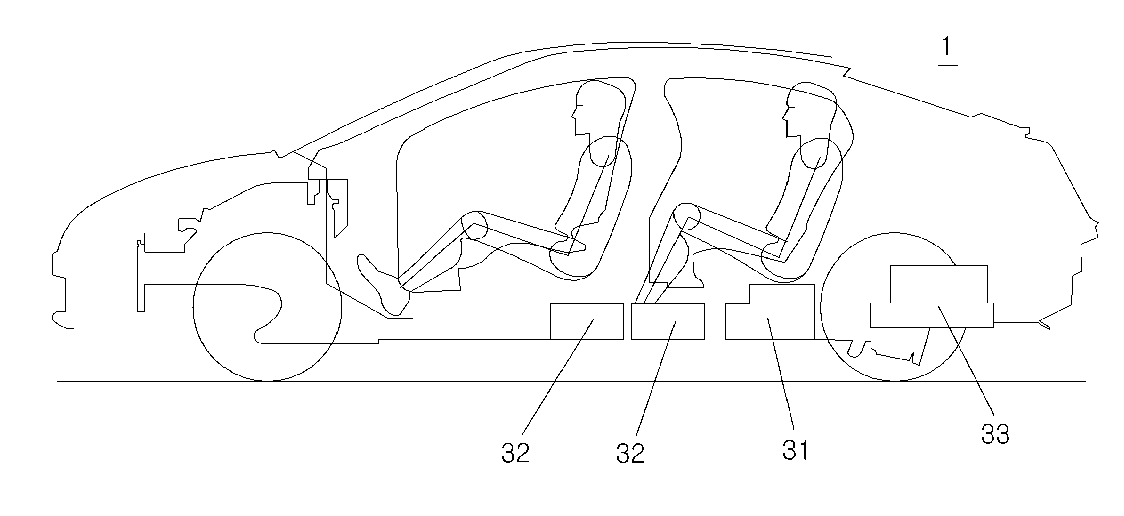
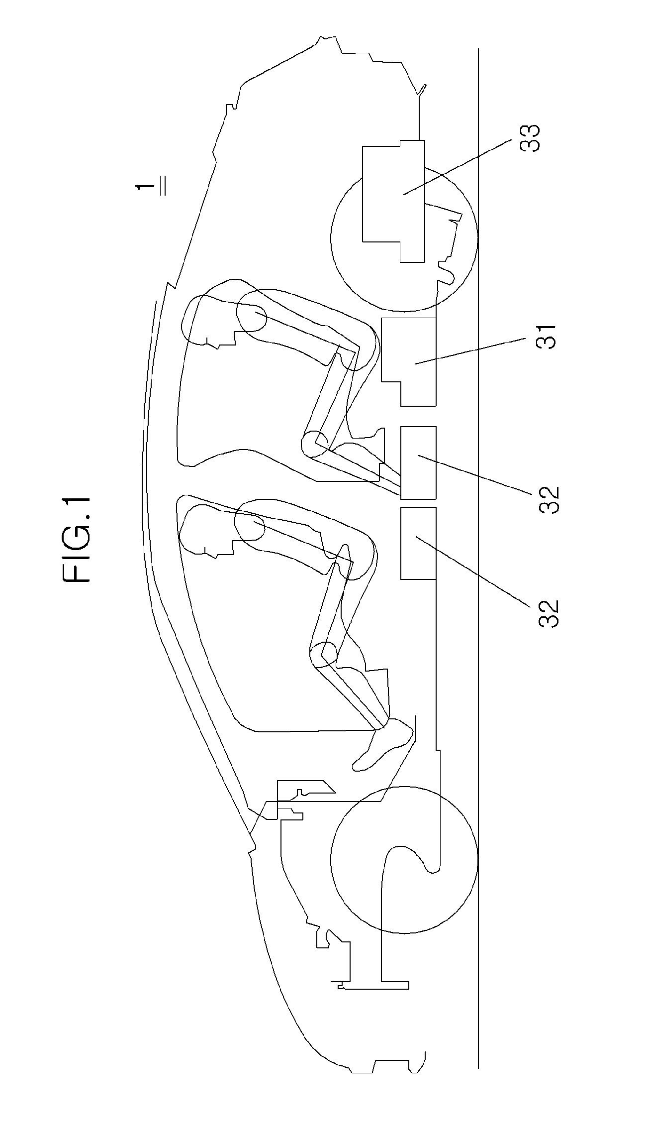
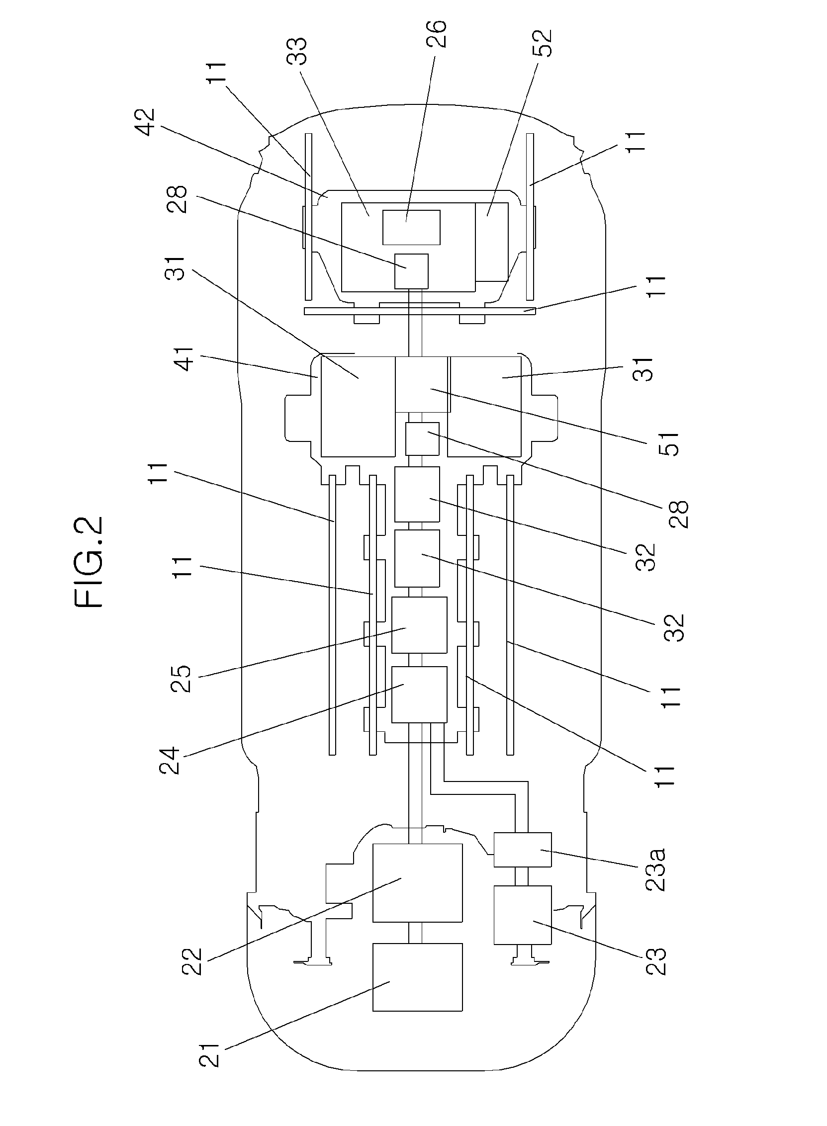
[0025]It is understood that the term “vehicle” or “vehicular” or other similar term as used herein is inclusive of electric motor vehicles in general such as passenger automobiles including sports utility vehicles (SUV), buses, trucks, various commercial vehicles, watercraft including a variety of boats and ships, aircraft, and the li...


PUM


Abstract

Provided is a mounting structure for a battery in an electric vehicle capable of increasing a driving distance of the electric vehicle by mounting a plurality of battery modules in an existing vehicle body of en electric vehicle. The mounting structure for a battery in an electric vehicle according to an exemplary embodiment of the present invention includes a main relay box electrically connected with an inverter, a plurality of first battery modules mounted beneath the rear seats of the electric vehicle, and a main housing positioned between a pair of front seats in the electric vehicle and below the rear seat. More specifically, the main housing is configured to house the main relay box and first battery modules therein, and is fixed to the vehicle body of the electric vehicle.

Description

CROSS-REFERENCE TO RELATED APPLICATIONS[0001]The present application claims priority to Korean Patent Application Number 10-2011-0072559 filed Jul. 21, 2011, the entire contents of which application is incorporated herein for all purposes by this reference.BACKGROUND OF THE INVENTION[0002]1. Field of the Invention[0003]The present invention relates to a structure in which a battery is mounted inside an electric vehicle, and more particularly, to a mounting structure for a battery in an electric vehicle capable of increasing a driving distance of the electric vehicle by mounting a plurality of battery modules in a vehicle body.[0004]2. Description of Related Art[0005]In recent years, hybrid vehicles and electric vehicles have quite popular due to high oil prices and the environmental impact of purely fuel consumption vehicles. In particular, the hybrid vehicle has become an intermediate choice for those consumers wishing to reduce fuel consumption while at the same time increase thei...

Claims


Application Information

Patent Timeline
Patent Type & Authority Applications(United States)
IPC IPC(8): B60K1/04B60K11/06
CPCB60K1/04B60K2001/003B60K2001/0433B60K2001/0427B60K2001/0416Y02T10/70B60L50/66B60K2001/0405B60K2001/005B60L2200/00B60Y2200/91
Inventor KIM, MINWOOKKIM, DALYOON, SHINHYUK
Owner HYUNDAI MOTOR CO LTD
Why Eureka
Try Eureka