Normally closed solenoid valve

Inactive Publication Date: 2013-01-24
ADVICS CO LTD
View PDF2 Cites 16 Cited by
  • Summary
  • Abstract
  • Description
  • Claims
  • Application Information

AI Technical Summary

Benefits of technology

[0014]According to the present invention, the damper for damping vibration of the movable element is formed by a cylinder formed in one of the valve housing and the movable member and a piston provided on the other of the valve housing and the movable member, and the cylinder has an inner diameter smaller than the outer diameter of the truck of the movable element. Thus, compared to the conventional arrangement of Patent document 1, or another conventional arrangement in which the damper chamber is defined between a piston which also serves as the movable element and the valve housing, it is possible to reduce the amount of change in volume of the damper chamber as the movable member moves by a predetermined stroke.
[0015]This makes it possible to reduce the restricted passage compared to the above conventional arrangements, without deteriorating the damper function of

Problems solved by technology

The volume of such a damper chamber changes to a considerable degree with the movement of the movable element,

Method used


Image

  • Normally closed solenoid valve
  • Normally closed solenoid valve
  • Normally closed solenoid valve

Examples


Example

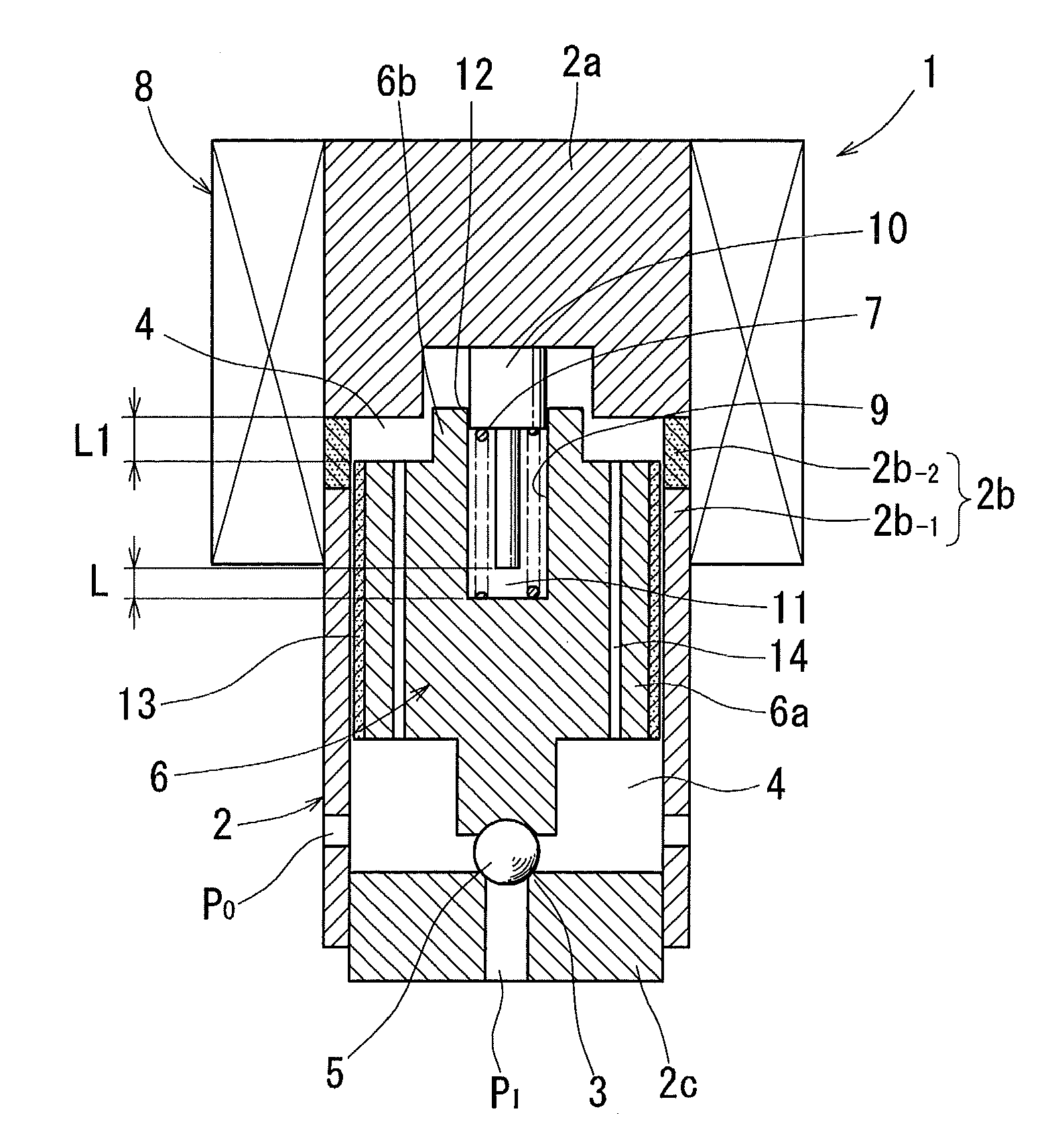
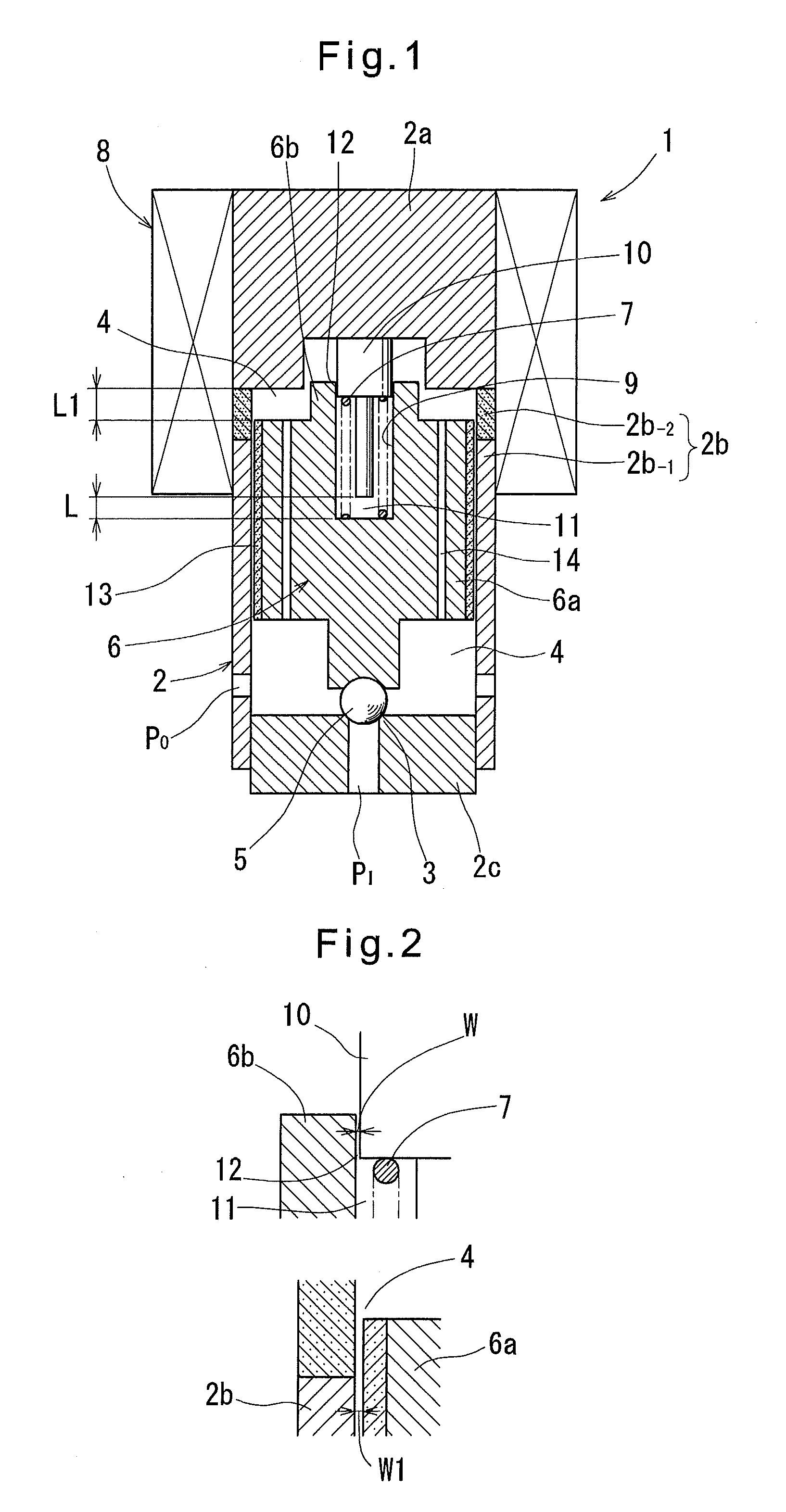
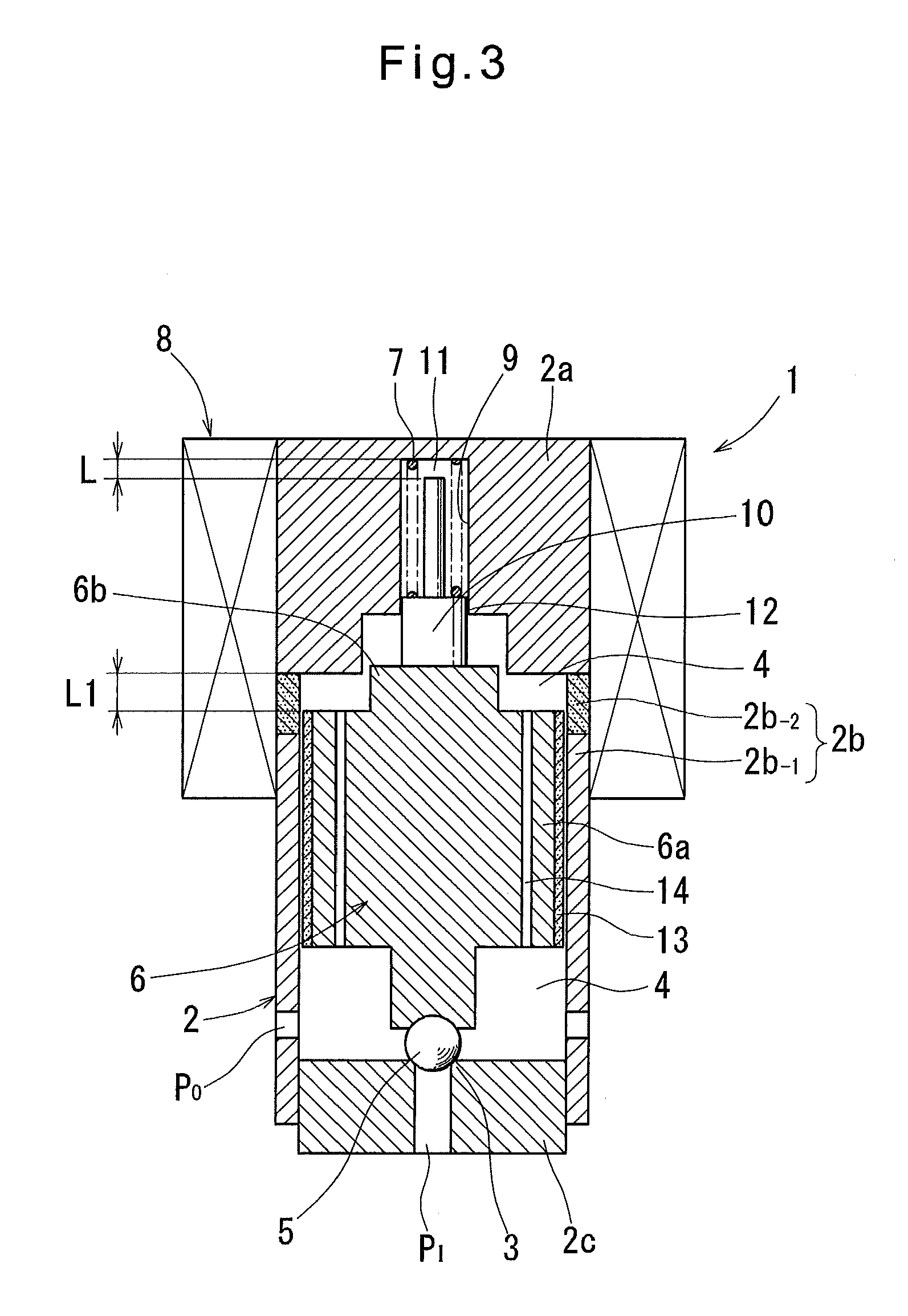
[0027]Now the various solenoid valves embodying the present invention are described with reference to the drawings. First, the solenoid valve 1 shown in FIG. 1 includes a valve housing 2 having a seating surface 3 and defining a valve chamber 4, a valve body 5 mounted in the valve chamber 4 and configured to be moved into and out of contact with the valve seat 3, a movable element (also generally called a “movable core”) 6 made of a magnetic material and mounted in the valve chamber 4, a spring 7 biasing the movable element 6 in a valve closing direction, and a solenoid 8.

[0028]The valve housing 2 comprises a fixed core 2a, a cylindrical member 2b defining the outer contour of the valve chamber 4, and a valve seat 2c closing the open end of the valve chamber 4. The seating surface 3 is formed on the valve seat 2c. The valve seat 2c is further formed with an inlet port PI communicating with the valve chamber 4. The cylindrical member 2b is formed with an outlet port PO also communica...


PUM


Abstract

To minimize the amount of air that may enter the damper chamber in a normally closed solenoid valve to stably maintain the damper capacity, the normally closed solenoid valve has a valve housing and a movable element. A cylinder having an open end is formed in one of the valve housing and the movable element. The cylinder has an inner diameter smaller than the outer diameter of a trunk of the movable element. A piston provided on the other of the valve chamber and the movable element is movable relative to the cylinder as the movable member moves. The piston is inserted into the cylinder through its open end to define a damper chamber between the piston and the cylinder. A restricted passage is formed between the damper chamber and the valve chamber through which hydraulic fluid can be moved between the valve chamber and the damper chamber.

Description

TECHNICAL FIELD[0001]This invention relates to a normally closed solenoid valve mounted in hydraulic circuits such as vehicle brake hydraulic pressure control systems. More specifically, the invention is directed to a solenoid valve including damper chamber which can more effectively suppress or damp vibration of a movable member of the solenoid valve.BACKGROUND ART[0002]The below-identified Patent document 1 discloses a conventional solenoid valve of the above-described type. This solenoid valve includes a movable element (plunger) mounted in a body and to which the force of a spring is applied in the valve closing direction and a magnetic attraction force generated by energizing a coil is applied in the valve opening direction, to drive a valve body. An elastic member is disposed around the movable element to partition the interior of the body into a valve chamber and a damper chamber.[0003]The volume of the damper chamber is variable with the movement of the movable element. A re...

Claims


Application Information

Patent Timeline
IPC IPC(8): F16K31/02
CPCB60T13/36B60T13/683F16K31/0693F16K31/0689F16K31/0665B60T8/363
Inventor WATANABE, SHOTASASAKI, SHINKOBAYASHI, KAZUYUKIMIYAGI, TAKAHIRO
Owner ADVICS CO LTD
Why Eureka
Try Eureka