Cooling apparatus, cooling method, program, computer readable information recording medium and electronic apparatus

Inactive Publication Date: 2005-10-27
RICOH KK
View PDF4 Cites 21 Cited by
  • Summary
  • Abstract
  • Description
  • Claims
  • Application Information

AI Technical Summary

Benefits of technology

[0013] In the Peltier apparatus (cooling apparatus) according to the present invention, the driving power changing part changes the power value of the driving power to the cooling element at each predetermined time interval by the predetermined power value, and thus controls the power value of the driving power for driving the Peltier device (cooling element). Accordingly, it is possible to reduce a change amount in the driving voltage when driving the Peltier device, and thus, to prevent temperature difference between a heat generating surface and a heat sink surface of the Peltier device f

Problems solved by technology

However, in this method of the prior art, the analog feed back control circuit delays the detected temperature of the cooling target as mentioned above.
Accordingly, a relatively long time may be required (that is, a follow-up speed is slow) until the applying driving voltage is stabilized into a proper value upon turning-on of the Peltier device (at a time of rising up) or turning-off of the Peltier device (at a time of decaying down), or in response to a sharp temperature change occurring in the cooling target.
Therefore, for a case where a subsequent step is executed after this stabilization, processing delay may occur.
Furth

Method used


Image

  • Cooling apparatus, cooling method, program, computer readable information recording medium and electronic apparatus
  • Cooling apparatus, cooling method, program, computer readable information recording medium and electronic apparatus
  • Cooling apparatus, cooling method, program, computer readable information recording medium and electronic apparatus

Examples


Example

[0033] The first embodiment of the present invention is described.

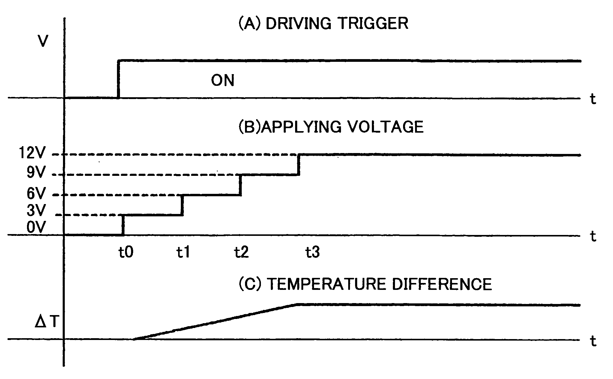
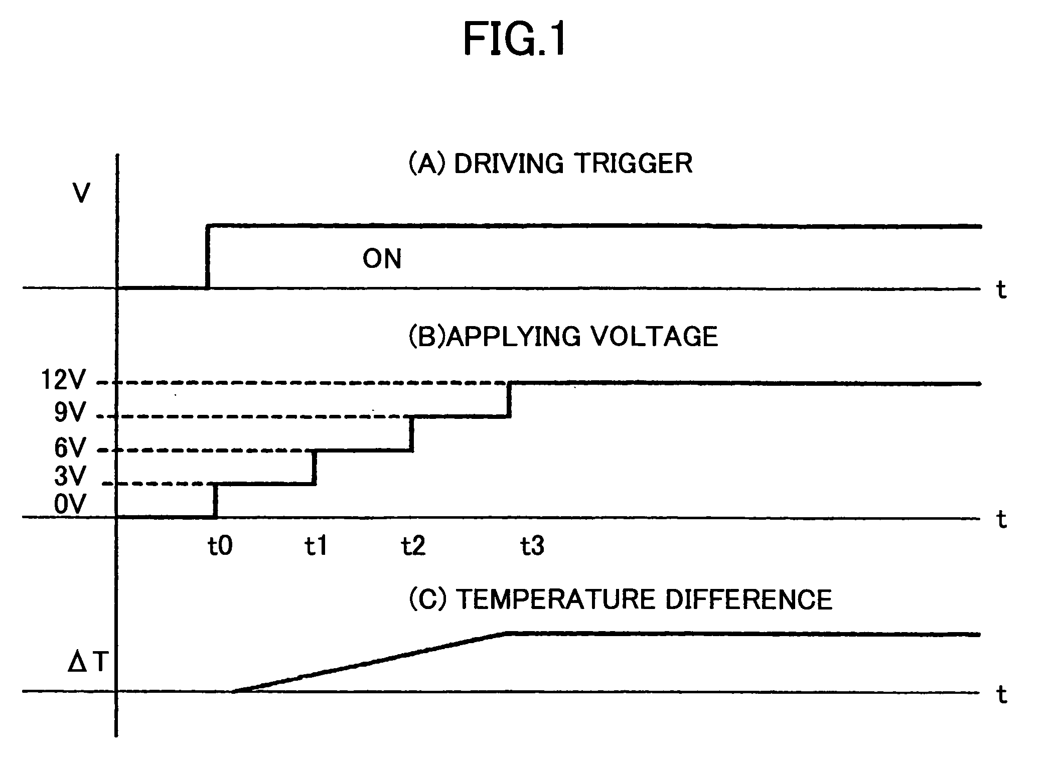
[0034] In this embodiment, as mentioned above, the applying voltage changing control manner is applied, in which the applying voltage for driving the Peltier device is changed.

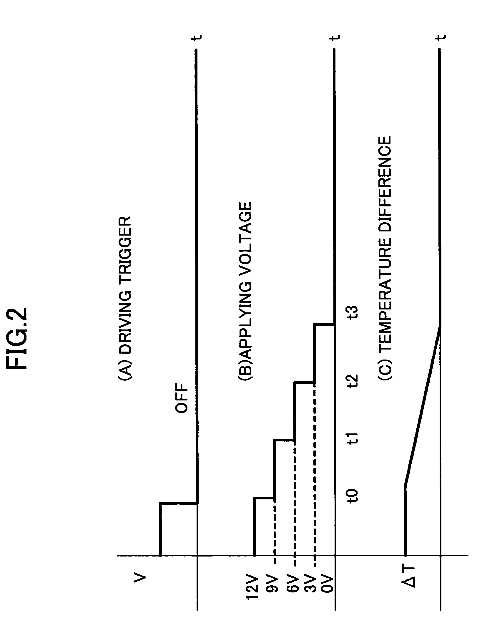
[0035] In this manner, upon turning on or turning off of power supply to an electronic apparatus, the applying voltage to the Peltier device is increased or decreased stepwise. In this control, a time interval for which each level of the applying voltage is output can be set arbitrarily as a control requirement, for the purpose of achieving the above-mentioned object of the present invention to optimize the operation control for each particular apparatus.

[0036]FIG. 1 illustrates operation according to the applying voltage changing control manner, specifically showing a time chart of a change in the applying voltage upon power supply tuning on, and a change of a temperature occurring from the Peltier device in response thereto. As shown in FIG...

Example

[0058] The above-mentioned second embodiment of the present invention is described now.

[0059] In this embodiment, as mentioned above, the PWM control manner is applied, in which the applying voltage for driving the Peltier device is changed.

[0060] In this manner, upon turning on or turning off of the power supply, the PWM duty is increased or decreased stepwise for a target value. In this control, a time interval for which each level of the applying voltage is output can be set arbitrarily as a control requirement, for the purpose of achieving the above-mentioned object of the present invention.

[0061]FIG. 5 illustrates operation according to the PWM control manner, specifically showing a time chart of a change in the applying voltage upon power supply tuning on, and a change of a temperature occurring in the Peltier device in response thereto. As shown in FIG. 5, (A), which shows a driving trigger signal for the Peltier device, a rising up (switching) of the driving trigger signa...

Example

[0082] A third embodiment of the present invention is described.

[0083] In this embodiment, the Peltier apparatus in the first or the second embodiment described above is actually applied in the electronic apparatus.

[0084] Since a cooing apparatus as the Peltier apparatus described above applying the Peltier device may have a effectively reduced size, and includes no mechanical moving element, such a cooling apparatus is suitable for avoiding temperature rise otherwise occurring due to a heat generated by circuit devices or such, a temperature or a humidity is thus controlled within a housing of an electronic apparatus and thus, an adequate operation environment can be kept, in the electronic apparatus in which an IC circuit, an electronic component, an electric unit or such for which a temperature or a humidity should be kept to a predetermined level is mounted in a narrow space within the housing. In the third embodiment, as an embodiment which can be preferably applied as such a...


PUM


Abstract

A cooling apparatus of supplying driving power to a cooling element from a power supply unit, to drive it, includes a driving power changing part changing a power value of the driving power supplied to said cooling element from the power supply unit, by a predetermined power value at each predetermined time interval.

Description

BACKGROUND OF THE INVENTION [0001] 1. Field of the Invention [0002] The present invention relates to a cooling apparatus such as a Peltier apparatus applying a cooling element such as a Peltier device, a cooling method, a program, a computer readable information recording medium such as a ROM, and an electronic apparatus such as an image forming apparatus in which the cooling method is applied. [0003] 2. Description of the Related Art [0004] Conventionally, a cooling apparatus applying a Peltier device, having a reduced size and including no mechanical moving parts, is therefore employed for avoiding temperature rise otherwise occurring due to heat generated by circuit devices and properly controlling a temperature environment, within an apparatus in which IC devices, electronic devices, electrical components or such are assembled within a narrow space inside of a housing (such an apparatus being referred to as an ‘electronic apparatus’ hereinafter). For example, Japanese Laid-open ...

Claims


Application Information

Patent Timeline
IPC IPC(8): B41J29/377F25B1/00F25B21/02F25B49/00G03G21/20
CPCB41J29/377F25B2321/0212F25B21/02
Inventor IWASAKI, HIROYUKI
Owner RICOH KK
Why Eureka
Try Eureka