

Optical Receiver Module
- Summary
- Abstract
- Description
- Claims
- Application Information
AI Technical Summary
Benefits of technology
Problems solved by technology
Method used
Image

Examples
Embodiment Construction
]
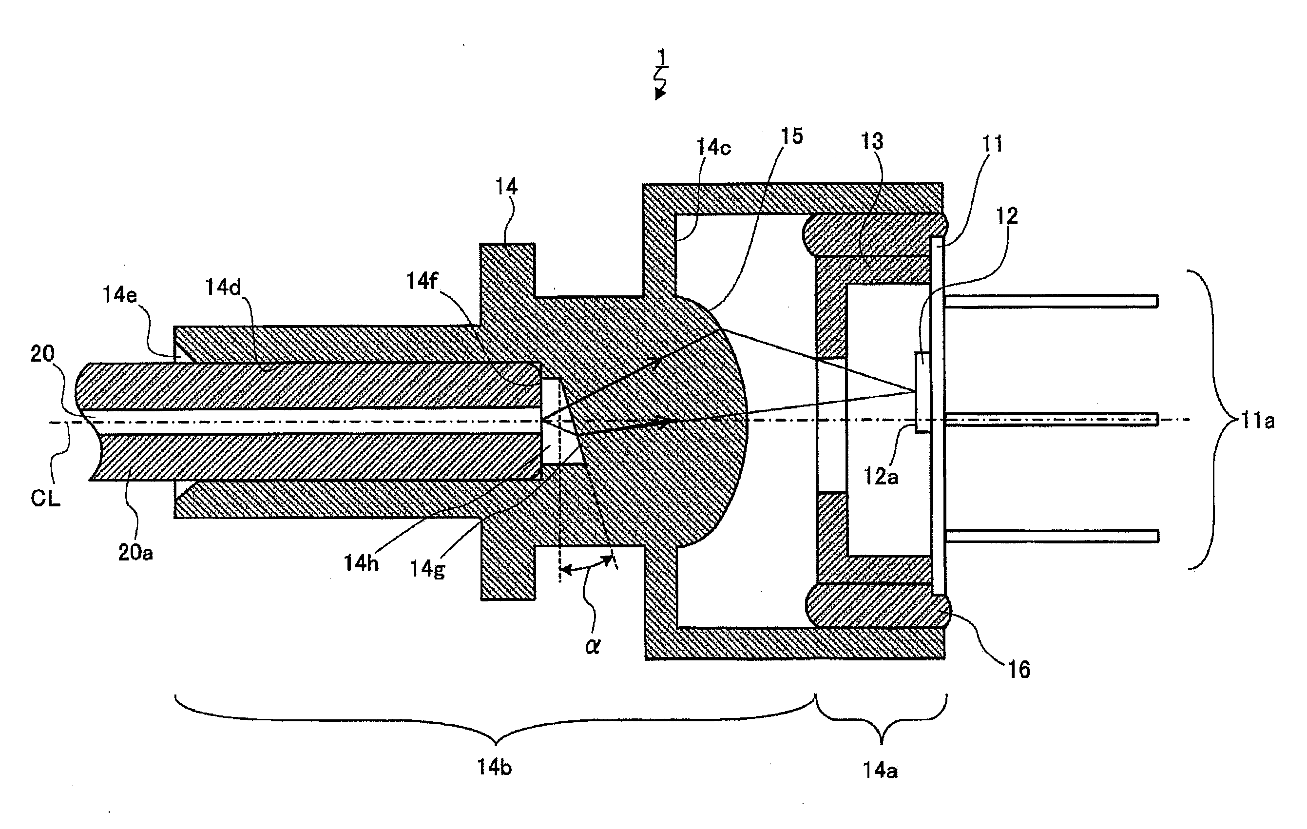
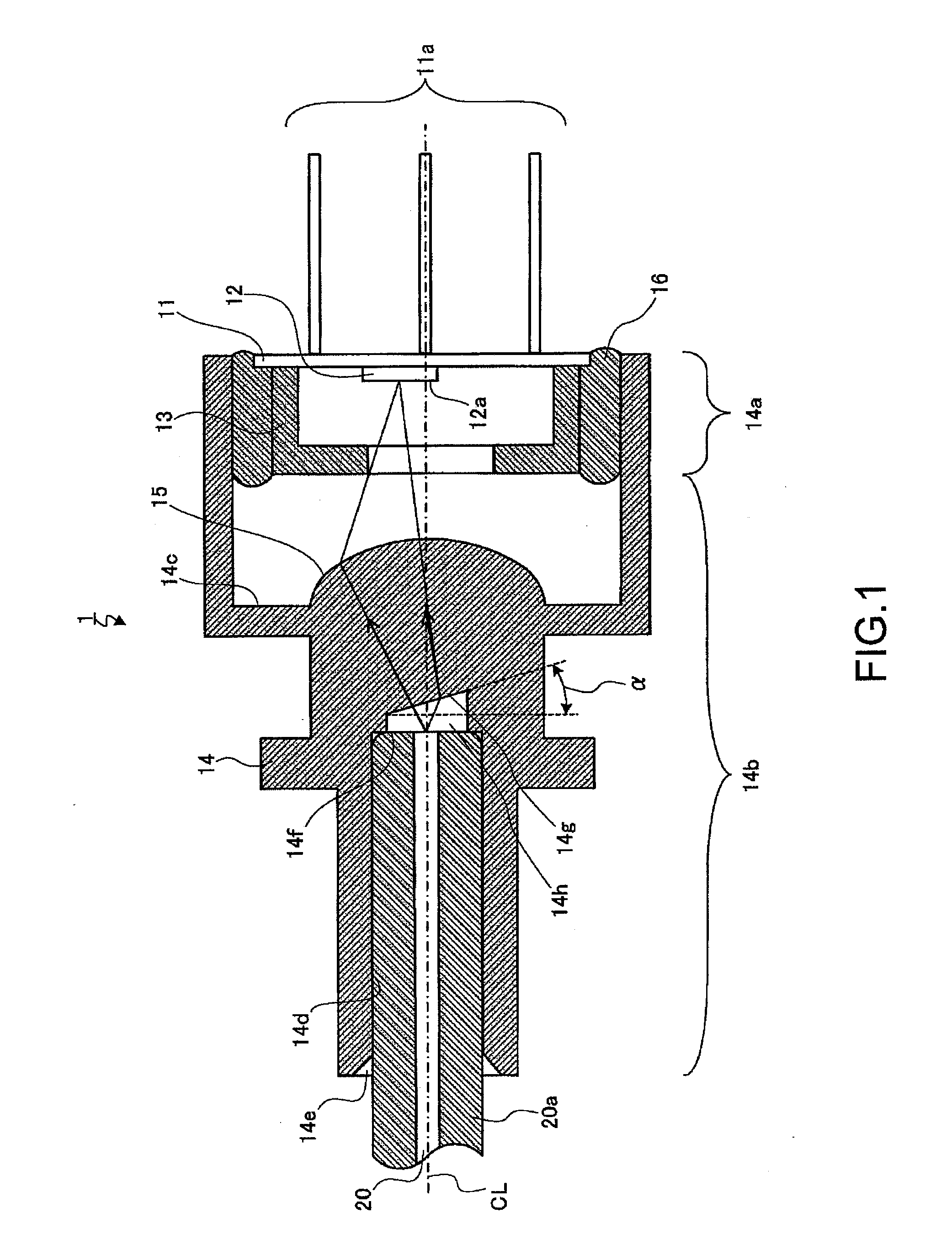
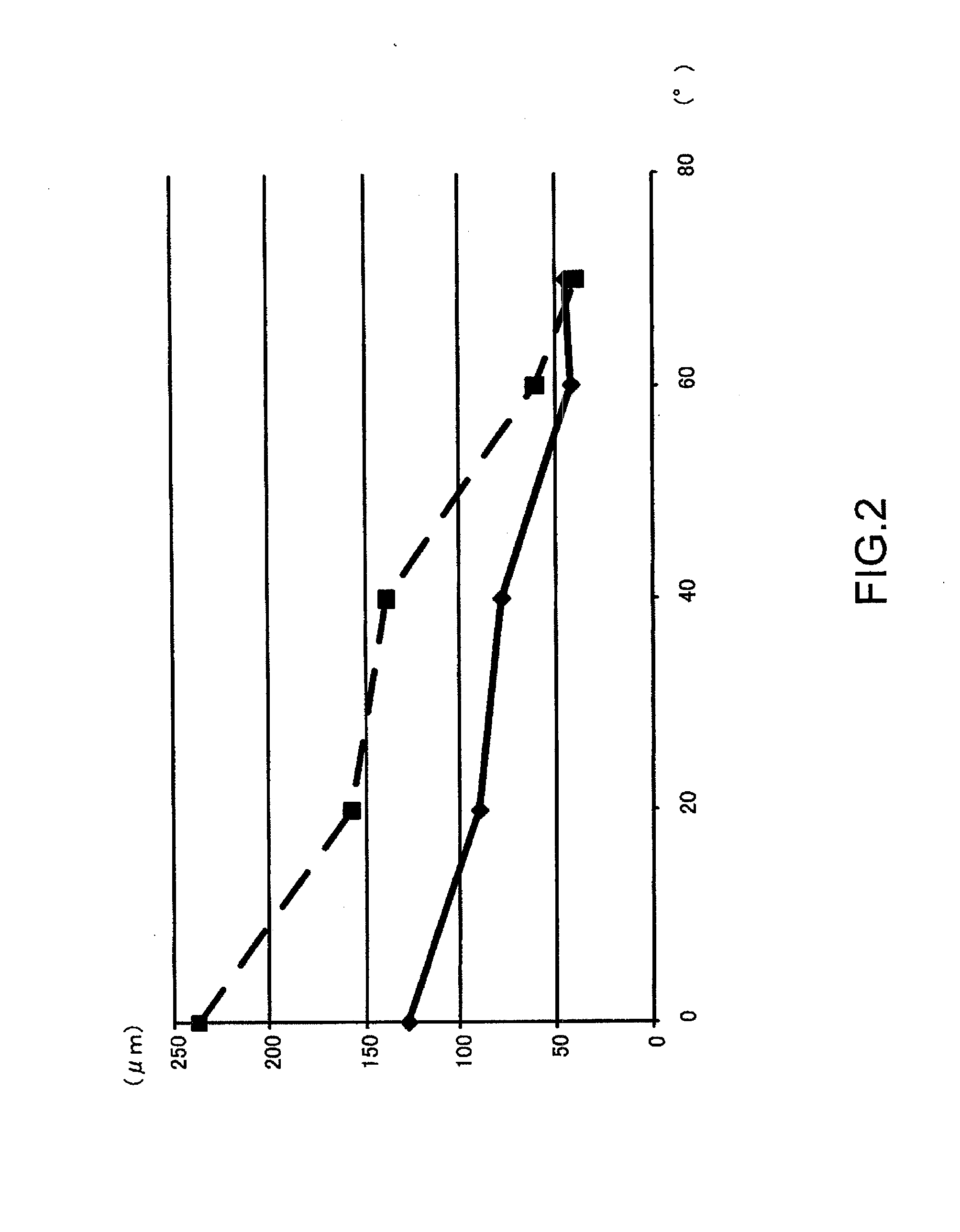
[0041]As described above, according to the present embodiment, the optical flat surface 14g is tilted by 20° to 40° or by 60° to 70° in relation to the light-receiving surface 12a of the light-receiving element 12. As a result, the direction of the reflected returning light can be changed, and the amount of reflected returning light entering the optical fiber can be suppressed. In addition, the amount of change in the light converging point in relation to temperature change can be reduced, and the amount of changes in performance due to variations during manufacture can be reduced. As a result, the accuracy required when centering the light-receiving element in the optical axis direction can be reduced, thereby preventing deterioration in optical performance due to temperature change at low cost and with a high yield rate.
[0042]In Patent Literature 1, the tilt angle of the optical flat surface in relation to the light-receiving element is 4° to 12°. A first reason for this is that,...
PUM
 Abstract
Description
Claims
Application Information