
Circuit arrangement and method for interrupting a current flow in a DC current path

a dc current path and circuit arrangement technology, applied in emergency protection devices, air break switches, relays, etc., can solve problems such as high current, ac current path oscillation, and burden system reliability, and electrical arc current may rise very fas

Active Publication Date: 2013-01-24
HITACHI ENERGY SWITZERLAND AG
View PDF4 Cites 47 Cited by
  • Summary
  • Abstract
  • Description
  • Claims
  • Application Information

AI Technical Summary

Benefits of technology

The patent describes a circuit arrangement for interrupting a current flow in a DC current path that includes two switching elements connected in series. Additionally, a resonance circuit is connected in parallel or can be connected using a switch to the series connection of the two switching elements. The first switching element can be an oil circuit breaker, a minimum oil circuit breaker, a strong blow electric arc, a splitter blade, or an FCS commutation switch. The patent also provides a method for interrupting a current flow in a DC current path by detecting an interrupt scenario and opening one of the switching elements. A resonance circuit can then be connected in parallel to the series connection of the two switching elements. The technical effect of this patent is to provide a more efficient and reliable circuit arrangement for interrupting a current flow in a DC current path.

Problems solved by technology

In such grids, a fault current may rise very fast in case of a short circuit and as a result may burden the system reliability.
However, due to the nature of the AC driving source, such ongoing electric arc current in the AC current path may oscillate, too, and inherently may show current zero crossings.

Method used


Image

  • Circuit arrangement and method for interrupting a current flow in a DC current path
  • Circuit arrangement and method for interrupting a current flow in a DC current path
  • Circuit arrangement and method for interrupting a current flow in a DC current path

Examples


Embodiment Construction

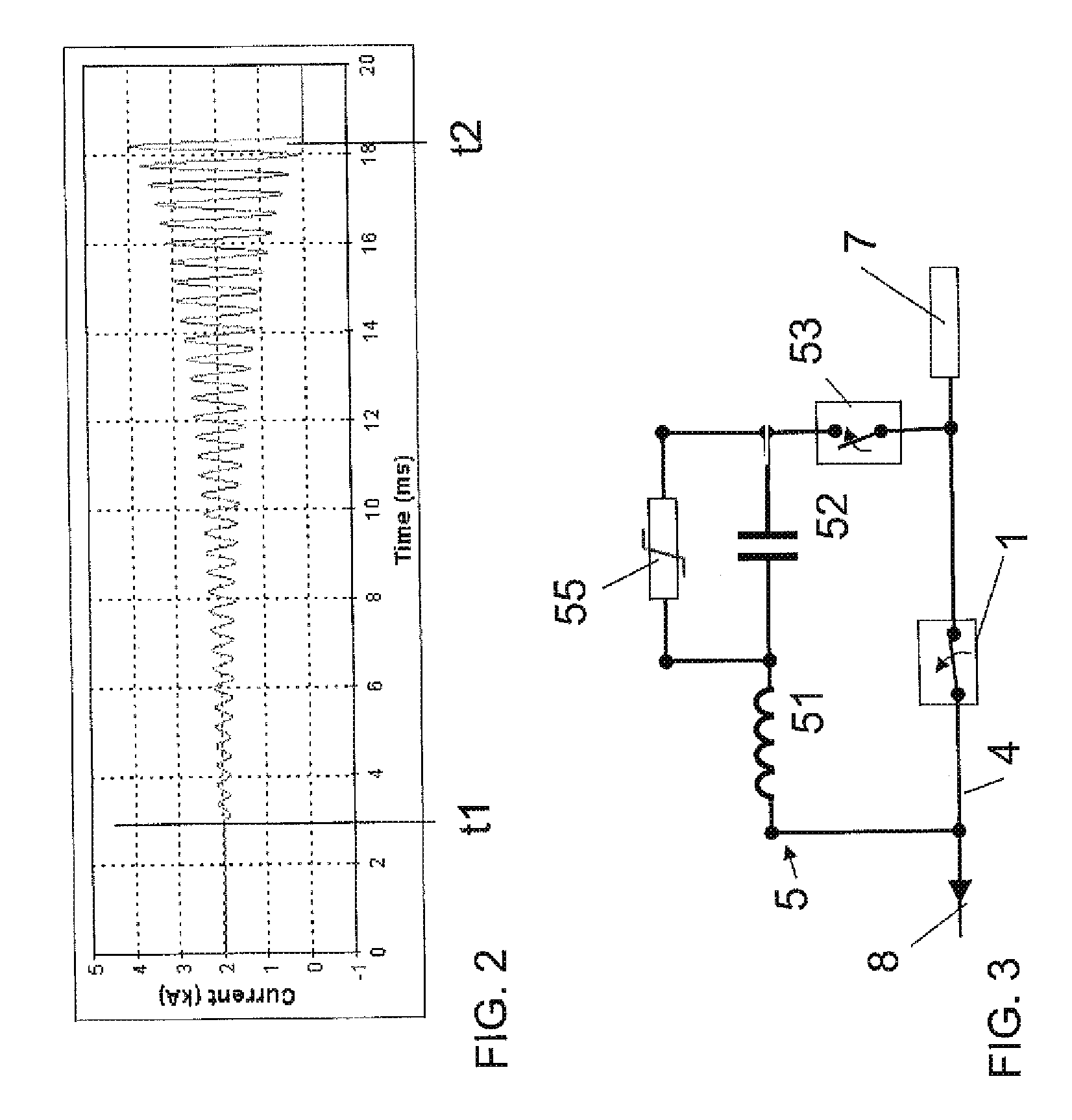
[0017]Exemplary embodiments of the present disclosure provide a circuit arrangement and method which reduce the time to generate a current zero in a DC current path.

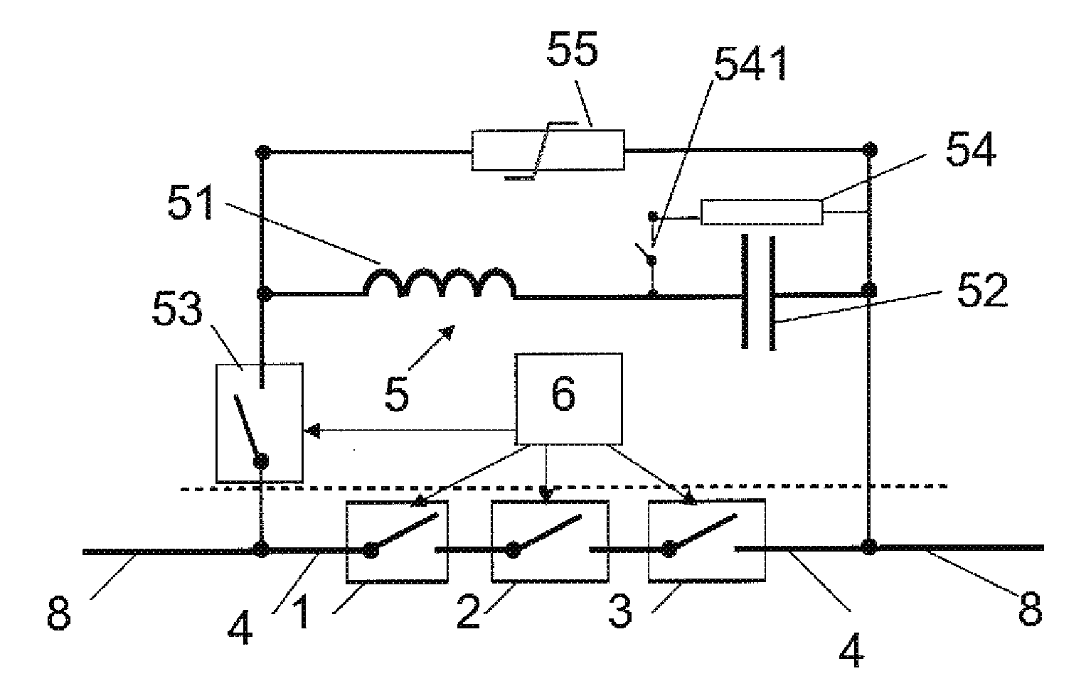
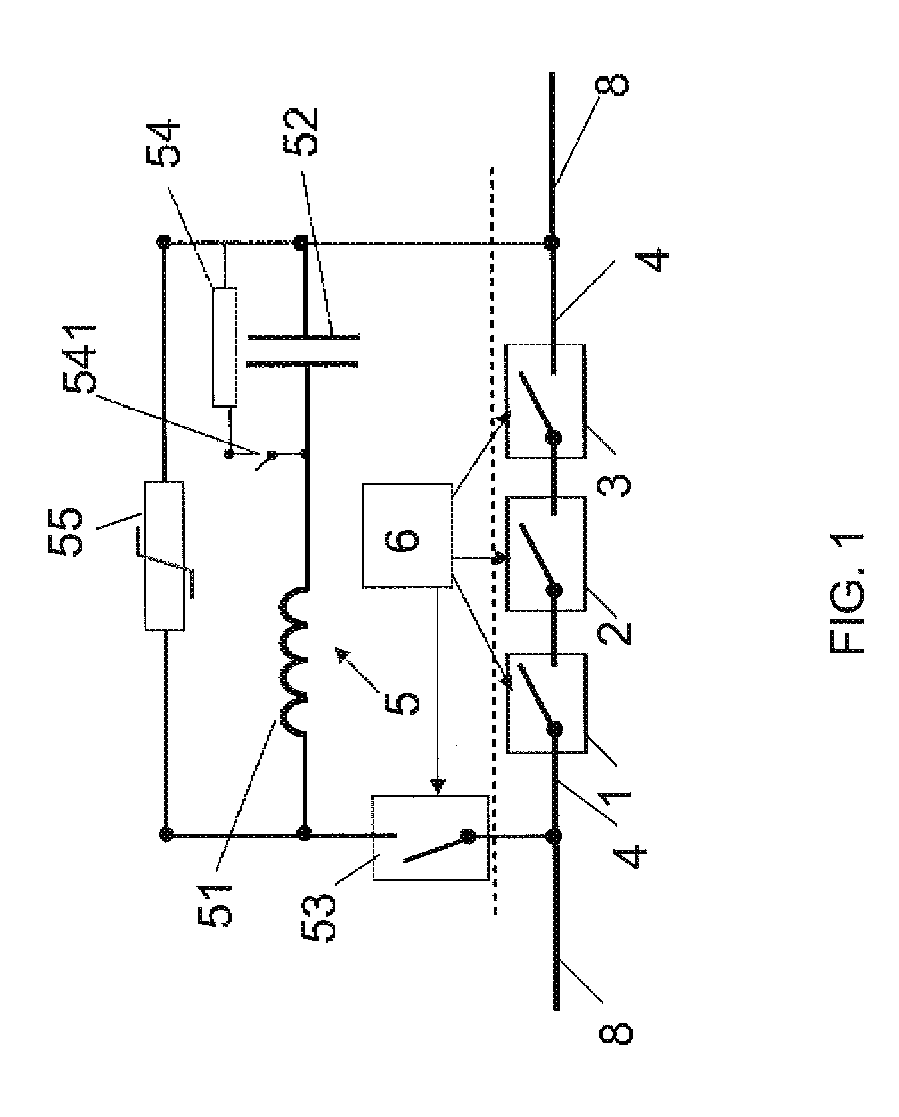
[0018]According to an exemplary embodiment of the present disclosure, a circuit arrangement is provided for interrupting a current flow in a DC current path. The circuit arrangement includes at least a first switching element and a second switching element connected in series in the DC current path. A resonance circuit is connected or is configured to be connectable in parallel to the series connection of the at least first switching element and second switching element by means of a switch.

[0019]According to an exemplary embodiment of the present disclosure representing a method, an interrupt scenario is detected for the DC current path including at least a first switching element and a second switching element connected in series. An open state of the at least first switching element and second switching element is eff...


PUM


Abstract

A DC current path for DC power transmission includes at least a first switching element and a second switching element connected in series. A resonance circuit is configured to be connectable in parallel to the series connection of the at least one first switching element and second switching element by means of a switch.

Description

RELATED APPLICATION[0001]This application claims priority under 35 U.S.C. §119 to European Patent Application No. 11165772.2 filed in Europe on May 12, 2011, the entire content of which is hereby incorporated by reference in its entirety.FIELD[0002]The present disclosure relates to high voltage (HV) direct current (DC) transmission, and more particularly, to a circuit arrangement and a method for interrupting a current flow in a DC current path.BACKGROUND INFORMATION[0003]High voltage direct current transmission grids for transmitting energy on a large scale are regaining attention for various reasons. The re-advent of DC grids is strongly linked to a different concept of how to drive power into the DC grid. Future DC grids may be controlled by a voltage controlled source, also known as voltage source converters (VSC). In such grids, a fault current may rise very fast in case of a short circuit and as a result may burden the system reliability.[0004]In the event of a short circuit i...

Claims


Application Information

Patent Timeline
IPC IPC(8): H01H47/00
CPCH01H33/75H01H33/596
Inventor PANOUSIS, EMMANOUILKOSTOVIC, JADRANLILJESTRAND, LARSBUJOTZEK, MARKUSSKARBY, PER
Owner HITACHI ENERGY SWITZERLAND AG
Features
  • Generate Ideas
  • Intellectual Property
  • Life Sciences
  • Materials
  • Tech Scout
  • Unparalleled Data Quality
  • Higher Quality Content
  • 60% Fewer Hallucinations
Learn More