Wearable display devices

a display device and wearable technology, applied in the field of wearable display devices, can solve the problems of large and heavy complete systems, reduced display screen image resolution, and insufficient high resolution screen image suited to full motion video, and achieve the effect of not affecting the quality of full motion video

Inactive Publication Date: 2013-01-24
BELL JONATHAN ARNOLD
View PDF26 Cites 140 Cited by
  • Summary
  • Abstract
  • Description
  • Claims
  • Application Information

AI Technical Summary

Benefits of technology

[0003]One object of the present invention is to provide a design for a wearable display device that allows the image from a semi-transparent display screen placed close to the eye to be correctly focused onto the retina while simultaneously allowing the image from the external environment to pass through the device without significant aberration.
[0005]A further object of the invention is to provide a design for a wearable display device that can overcome any far- or near-sightedness present in the wearer.
[0011]A further object of the invention is to provide a design for a wearable display device that can detect images of the external environment in various wavelength bands and estimate relative distances of various objects in view.

Problems solved by technology

Due to the relatively large size of these individual components the complete systems are generally large and heavy.
While this allows a relatively clear view through the device, the display screen image resolution is very much reduced and may not be sufficient to produce a high resolution screen image suited to full motion video.

Method used


Image

  • Wearable display devices
  • Wearable display devices
  • Wearable display devices

Examples


Embodiment Construction

:

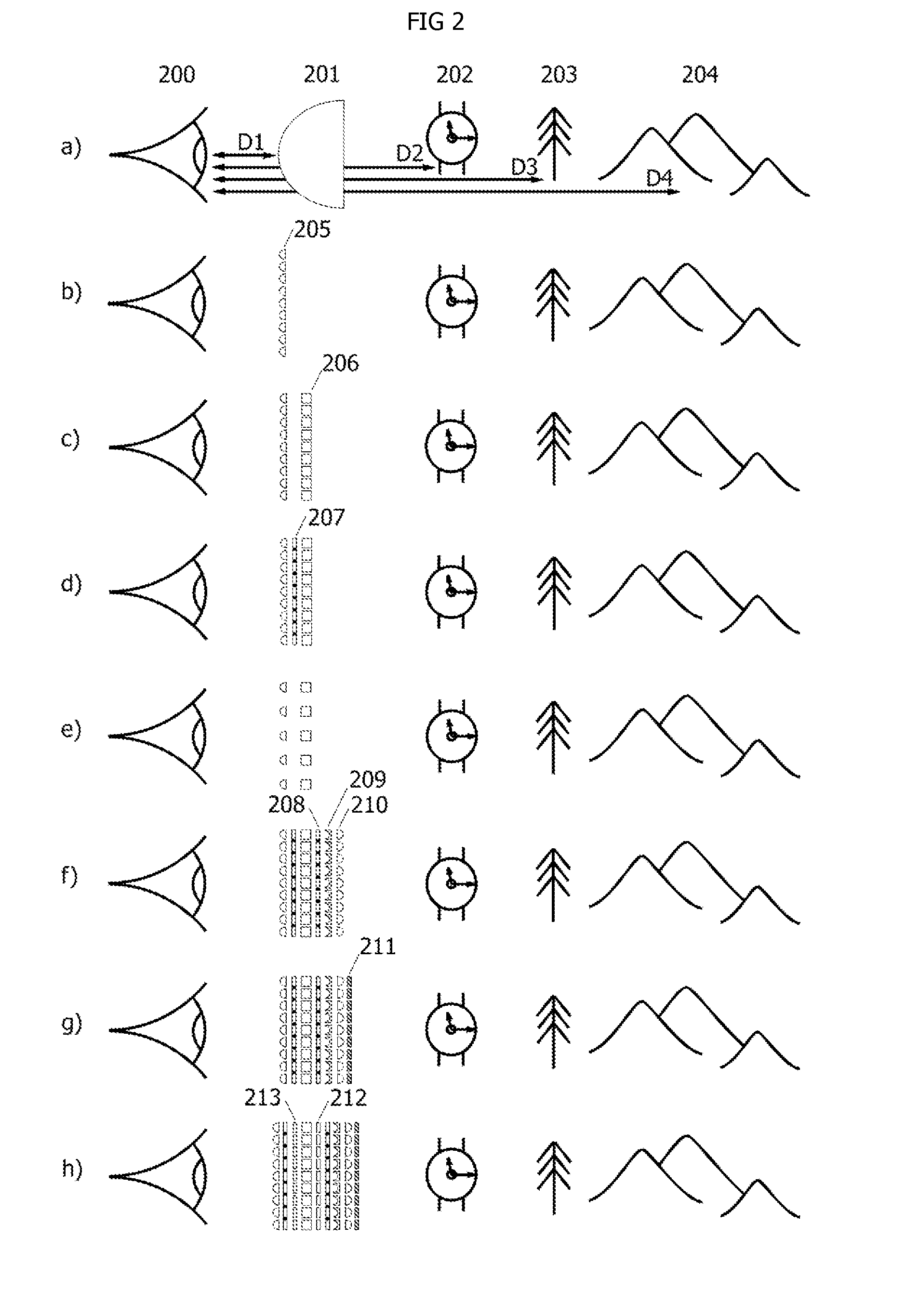
[0034]As a means of introduction to the subject of wearable display devices, FIG. 2(a) illustrates a typical bulk convex lens optic 201 placed at a close distance D1 to the eye 200 for purposes of correcting far-sightedness so that an object such as a wrist watch 202 near to the eye at a distance D2 can be focused correctly to the eye. For near-sightedness, convex lens 201 would be replaced with a concave lens so that objects such as mountains 204 far from the eye at a distance D4 can be focused correctly to the eye. A tree 203 at a middle distance D3 may or may not require any corrective lens 201 for proper focusing. If a convex lens 201 is used in a pair of eye glass frames then the convex surface distance D1 may be as close as 0.5 inches from the pupil of the eye 200, the wrist watch 202 may be at a distance D2 of 2 feet, the tree 203 may be at a distance D3 of 10 feet to 100 feet, and the mountains 204 may be at a distance D4 of 1,000 feet to 10,000 feet. FIG. 2(b) illustrates ...


PUM


Abstract

A wearable display device is described that allows the image from a semi-transparent display screen placed close to the eye to be correctly focused onto the retina while simultaneously allowing the image from the external environment to pass through the device without significant aberration. Focus of the display screen image is achieved through use of a micro-lens array between the screen and the eye, and a separate set of micro-lens arrays on the distant side of the screen in conjunction with the micro-lens array on the near side of the screen allows the external environmental image to pass through. In this manner images from the display screens can overlay the eye's usual view of the external environment. Use of micro-lens arrays that have dynamically adjustable focus properties allow for simulated three-dimensional images and corrective optics for far- or near-sightedness.

Description

CROSS-REFERENCE TO RELATED APPLICATION[0001]This application claims priority to U.S. Provisional Patent Application Ser. No. 61 / 510,185 to Jonathan Arnold Bell Entitled “Wearable Display Devices”.BACKGROUND OF THE INVENTION:[0002]Previous inventions relating to wearable display devices and head mounted displays (HMDs) have used bulk optics such as lenses, mirrors, prisms, beam splitters, and polarizers to achieve a partially see-through mechanism. Due to the relatively large size of these individual components the complete systems are generally large and heavy. Other efforts use integrated optics such as waveguides, grating structures, and Fresnel lenses to reduce size and weight. U.S. Pat. No. 5,499,138 by Iba (1996) shown in FIG. 1(a) introduces the concept of a micro-lens array to focus the light from a display screen located directly in front of the eye as a means to reduce the bulk of the lens structure and improve the optical clarity of the focused image but makes no mention o...

Claims


Application Information

Patent Timeline
Patent Type & Authority Applications(United States)
IPC IPC(8): G09G5/00
CPCG02B3/0006G02B27/017G02B2027/0138G02B2027/011G02B2027/0118G02B2027/0127
Inventor BELL, JONATHAN ARNOLD
Owner BELL JONATHAN ARNOLD
Why Eureka
Try Eureka