Head mount display

a display and head mount technology, applied in the field of head mount displays, can solve the problems of reduced large size and weight of the plug-in module, and short so as to reduce the wearability of the eyeglass frame, reduce the operating time of the image display unit, and reduce the size of the battery

Active Publication Date: 2013-01-24
BROTHER KOGYO KK
View PDF14 Cites 14 Cited by
  • Summary
  • Abstract
  • Description
  • Claims
  • Application Information

AI Technical Summary

Benefits of technology

[0006]The plug-in module is connected to an eyeglass frame to the rear end of a temple of the eyeglass frame. Accordingly, if the plug-in module is compact and light-weight, the user needs to wear the eyeglass frame while setting the plug-in module at one of certain limited positions of the back of the head so that the plug-in module can be connected to the rear end of the temple of the eyeglass frame. That is, even when the plug-in module is compact and light-weight, the user needs to wear the eyeglass frame while paying attention to the position of the plug-in module. Therefore, the wearability of the eyeglass frame is decreased. In addition, a small and light-weight plug-in module includes a relatively small capacity battery. Therefore, the operating time of the image display unit is relatively short, which is problematic.

Problems solved by technology

That is, even when the plug-in module is compact and light-weight, the user needs to wear the eyeglass frame while paying attention to the position of the plug-in module.
Therefore, the wearability of the eyeglass frame is decreased.
Therefore, the operating time of the image display unit is relatively short, which is problematic.
In contrast, if the capacity of the battery included in the plug-in module is relatively large, the plug-in module is large-sized and heavy.
Accordingly, the user feels unpleasant after wearing the eyeglass frame for a long time.
Thus, the long strap may interfere with the movement or the operation of the user wearing the eyeglass frame.

Method used


Image

  • Head mount display
  • Head mount display
  • Head mount display

Examples


first embodiment

[0028]A head mount display according to a first embodiment of the present disclosure is described below with reference to the accompanying drawings. The present embodiment represents only one of the aspects of the present disclosure, and any one of components may be replaced, added, and removed.

[0029]Overall External Structure

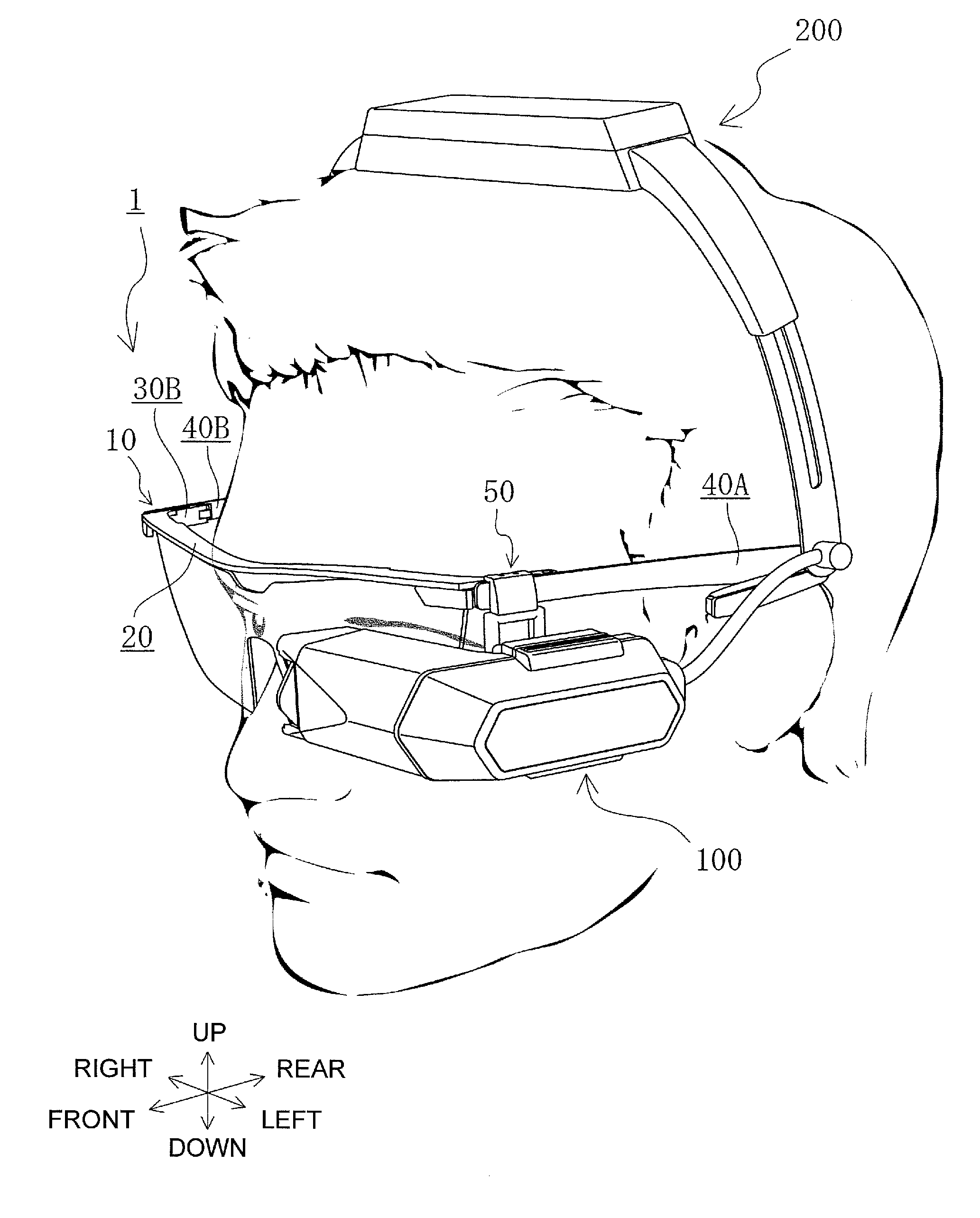
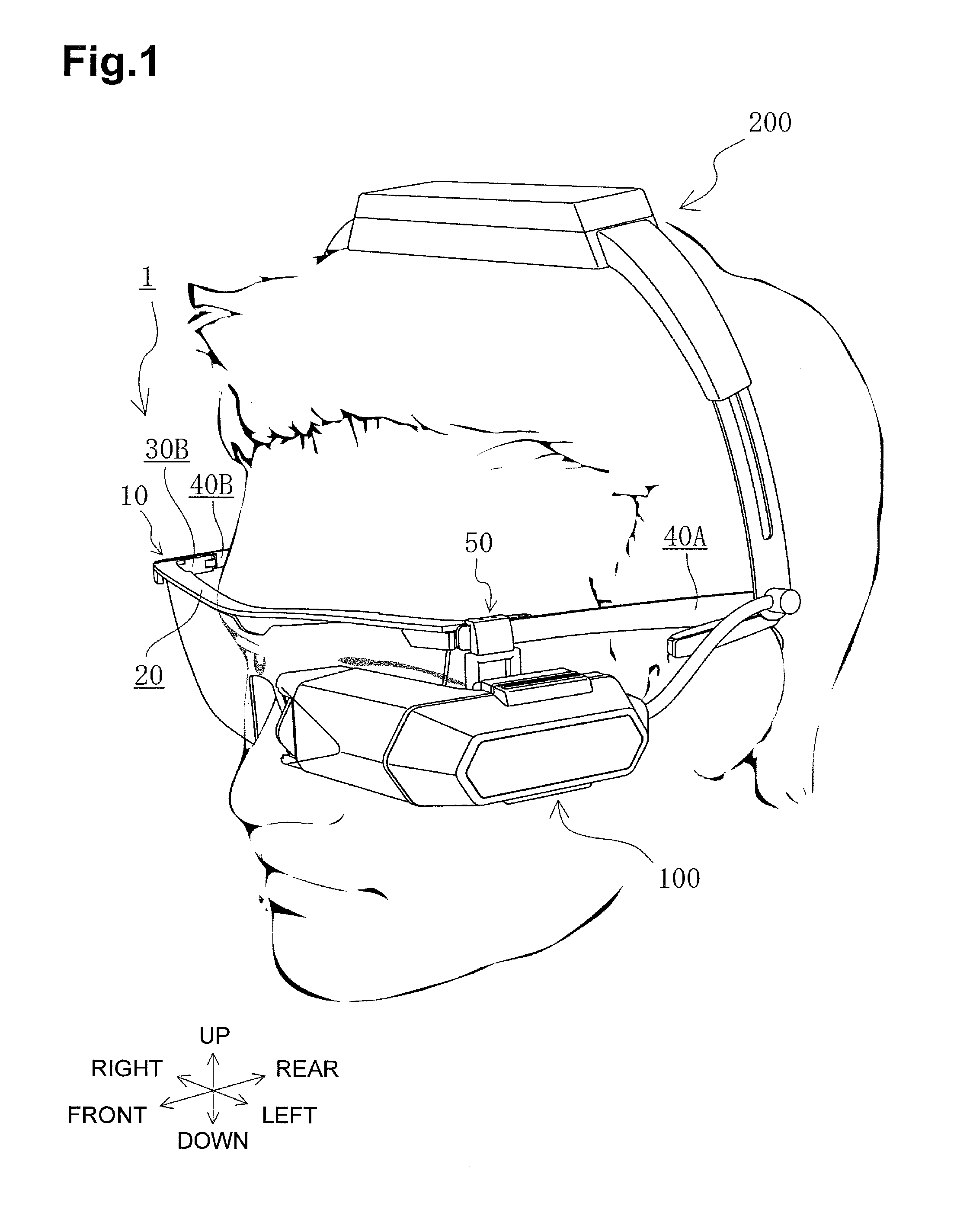
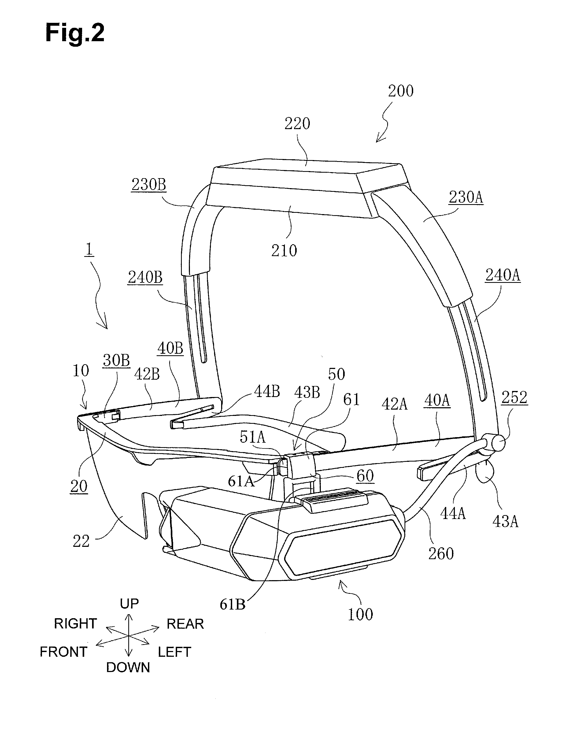
[0030]The overall external structure of a head mount display 1 according to the present embodiment is described below with reference to FIGS. 1 and 2. The head mount display 1 includes a first frame 10 of an eyeglass type, a support mechanism 50, a display 100 supported on the first frame 10 by the support mechanism 50, and a second frame 200 pivotably mounted on the first frame 10. The display 100 has a function of presenting a virtual image to a user. The display 100 includes, for example, a spatial light modulation element and an eyepiece optical system. For example, a liquid crystal display device or an organic electro-luminescence (EL) display device is us...

second embodiment

[0082]A second embodiment of the present disclosure is described below with reference to FIGS. 12 to 15. The second embodiment differs from the first embodiment in that a second frame is removably attached to the first frame. Hereinafter, only a structure that differs from that of the first embodiment is described. The same numbering is used for the elements that are the same as in the first embodiment.

[0083]As illustrated in FIGS. 12 and 13, the lower portion of a connection band 240A-1 is fork-shaped and has two leg portions 300 and 301. The leg portion 300 includes a pivot hole 302 and an opening 303 that opens downward. Similarly, the leg portion 301 includes a pivot hole 304 and an opening 305 that opens downward. Like the connection band 240A of the first embodiment illustrated in FIG. 7, the leg portion 300 illustrated in FIG. 12 has the conductor members 256P and 256N on the left side surface thereof, each of which is in the form of a circular arc with the center located at ...


PUM


Abstract

A head mount display includes a first frame, a display, a second frame, and a junction. The display is mountable on the first frame. The second frame is configured to be pivotably connected to the first frame and includes a circuit module. The circuit module includes a power circuit configured to supply power to the display. The junction is configured to electrically connect the display and the circuit module.

Description

CROSS-REFERENCE TO RELATED APPLICATION[0001]The present application is a Continuation-in-Part of International Application PCT / JP2011 / 056916, filed on Mar. 23, 2011, which claims the benefit of Japanese Patent Application No. 2010-076445, filed on Mar. 29, 2010, each of which is incorporated herein by reference.BACKGROUND OF THE DISCLOSURE[0002]1. Field of the Disclosure[0003]The present disclosure relates to a head mount display and, in particular, to a head mount display having a power supply that is mounted in a frame and that supplies electric power to a display.[0004]2. Description of the Related Art[0005]In recent years, a variety of head mount displays serving as mobile image display units used for game machines and mobile information terminal devices have been available in the market. In one of existing types of head mount display, devices, such as a microphone, a speaker, a camera, and a display, are mounted on an eyeglass frame. In order to operate these devices, a plug-in...

Claims


Application Information

Patent Timeline
Patent Type & Authority Applications(United States)
IPC IPC(8): G06F3/038
CPCG02B27/0176G02B2027/0178G02B2027/0156
Inventor WATANABE, MITSUYOSHIYASUE, NORIMIODA, MASANORI
Owner BROTHER KOGYO KK
Why Eureka
Try Eureka