

Illuminating device, projecting device, and method for controlling projecting device
a projecting device and projecting technology, applied in the field of projecting devices and projecting devices, can solve the problems of increasing the cost and device size, insufficient light amount, and deteriorating the characteristic of phosphor layers
- Summary
- Abstract
- Description
- Claims
- Application Information
AI Technical Summary
Benefits of technology
Problems solved by technology
Method used
Image

Examples
application example of first embodiment
[0058]FIG. 3 illustrates an example of a configuration of a projecting device 10 using the illuminating device 1 in FIG. 1. In FIG. 3, the same reference numerals denote parts common to those in FIG. 1, and a detailed description thereof is omitted. The projecting device 10 includes the illuminating device 1 that has been described with reference to FIG. 1, a controller 140, an interface 141, and a projection optical system. The projection optical system includes light collecting elements 130 and 132, a mirror 133, an integrator 131, an image generator 134, and a projecting lens 135.
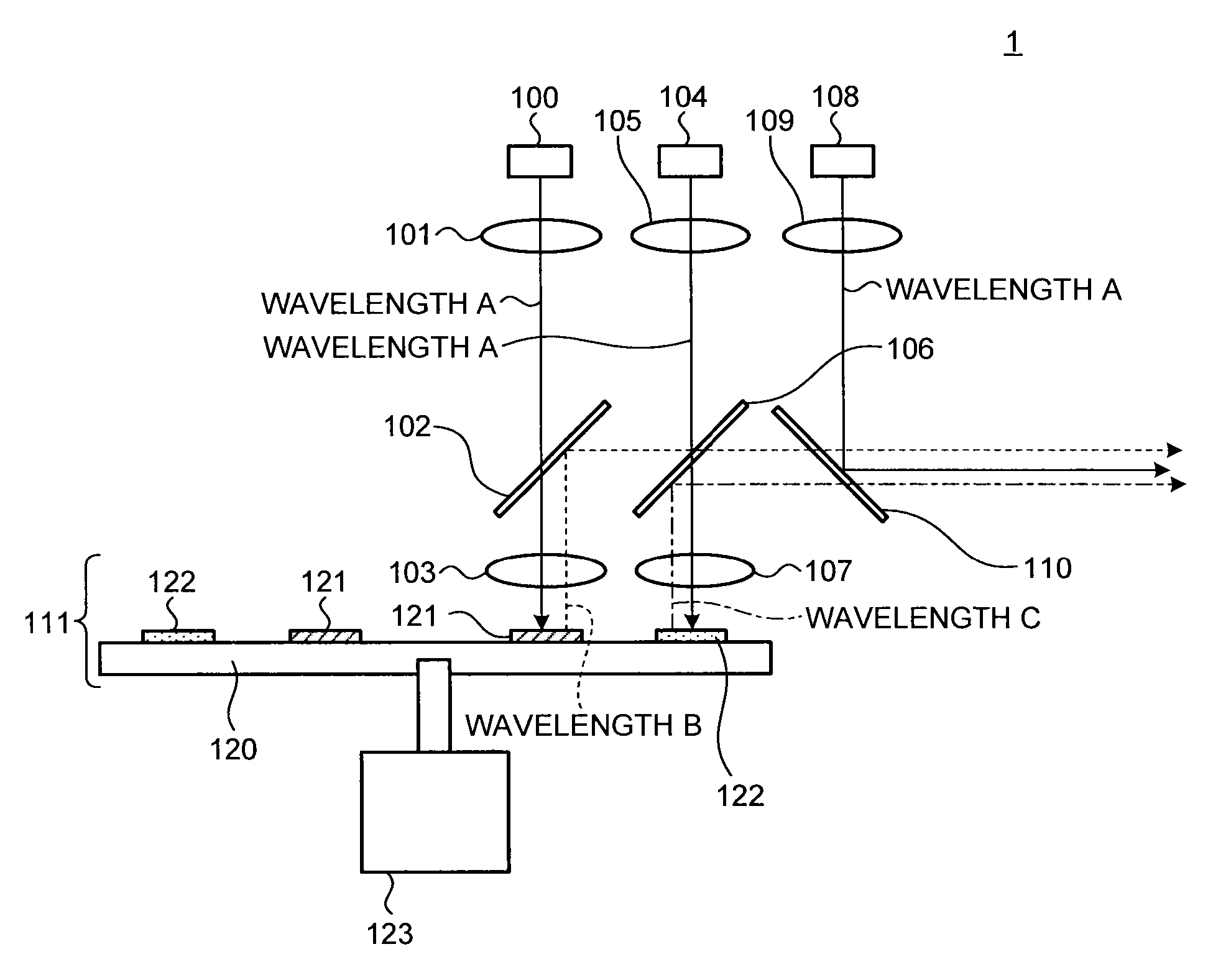
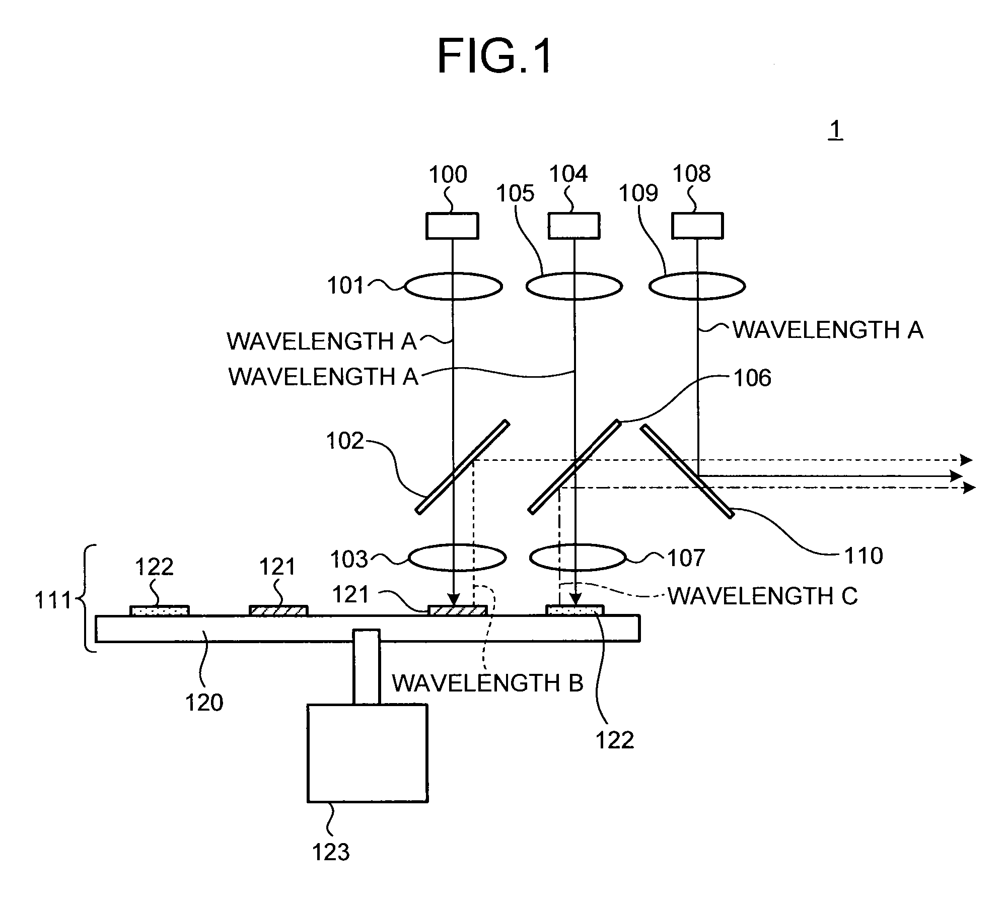
[0059]Since each of optical paths of light rays having the wavelength A that have been emitted from the light sources 100, 104, and 108 on the illuminating device 1 to be incorporated into the projecting device 10 is the same as each of the optical paths as described with reference to FIG. 1, description thereof is omitted.
[0060]On the projecting device 10, beams of light rays having the wavelengths A, B...
first embodiment
Fifth Variation of First Embodiment
[0127]Next, the fifth variation of the first embodiment is described. In the above-described first embodiment, a DMD is used as a light modulating element that forms an image in accordance with a modulation signal based on image data. In contrast, in the fifth variation of the first embodiment, a reflection-type liquid crystal panel is used as the light modulating element. In the reflection-type liquid crystal panel, a liquid crystal driving circuit is formed on a silicon substrate and liquid crystal is sandwiched between the silicon substrate and a transparent substrate opposed to the silicon substrate.
[0128]FIG. 12 illustrates an example of a configuration of a projecting device 10′ according to the fifth variation of the first embodiment. The illuminating device 1 as described with reference to FIG. 1 is incorporated in the projecting device 10′, as an example. It is to be noted that in FIG. 12, the same reference numerals denote parts common to...
second embodiment
Variation of Second Embodiment
[0149]Next, the variation of the second embodiment of the invention is described. In the above-described second embodiment, optical systems for the light sources 300 and 305 are configured such that a distance between irradiation positions of the light rays onto the phosphors 321 and 322 of the colors on the substrate 320 is the shortest. In contrast, in the variation of the second embodiment, optical systems for the light sources 300 and 305 are configured such that a distance between the irradiation positions is longer in the same manner as the above-described second variation of the first embodiment.
[0150]FIG. 14 illustrates an example of a configuration of an illuminating device 5 according to the variation of the second embodiment. In FIG. 14, the same reference numerals denote parts common to those in FIG. 13, and a detailed description thereof is omitted. In the variation of the second embodiment, a configuration of the substrate 320 to be used i...
PUM
 Abstract
Description
Claims
Application Information