Device for transmitting light energy and associated transmission method

a technology of light energy and transmission method, which is applied in the direction of lasers, optical devices for lasers, instruments, etc., can solve the problems of deteriorating unable to provide satisfaction, and degrading the spatial quality of beams leaving the fiber, etc., to achieve high energy and high robustness

Inactive Publication Date: 2013-01-24
MEGGITT FRANCE
View PDF11 Cites 30 Cited by
  • Summary
  • Abstract
  • Description
  • Claims
  • Application Information

AI Technical Summary

Benefits of technology

[0014]It is therefore one objective of the invention to provide a light power transmission device including an illuminating assembly and an optical fiber capable of transmitting pulses of high energy, in particular higher than one millijoule, the device being highly robust.

Problems solved by technology

However, the solution does not give satisfaction since the spatial quality of the beam is deteriorated, in particular on account of the increase in the number of guided modes.
However, these optical fibers have a core of large size to support numerous modes, which degrades the spatial quality of the beam leaving the fiber.
In addition, the fabrication of these fibers is difficult and available lengths are less than a few metres.
In addition, the size of the core of these fibers is very limited owing to fabrication stresses, which reduces power transmission.
Finally, part of the energy of the laser beam is propagated in the microstructuring (inner cladding) which is likely to degrade more particularly the silica bridges linking the tubes together, causing irreversible degradation of the fiber.

Method used


Image

  • Device for transmitting light energy and associated transmission method
  • Device for transmitting light energy and associated transmission method
  • Device for transmitting light energy and associated transmission method

Examples


Embodiment Construction

[0043]In the remainder hereof, the terms “upstream” and “downstream” are to be construed in relation to the normal direction of circulation of a light beam through the device.

[0044]A first energy transmission device 10 according to the invention is illustrated in FIGS. 1 and 2.

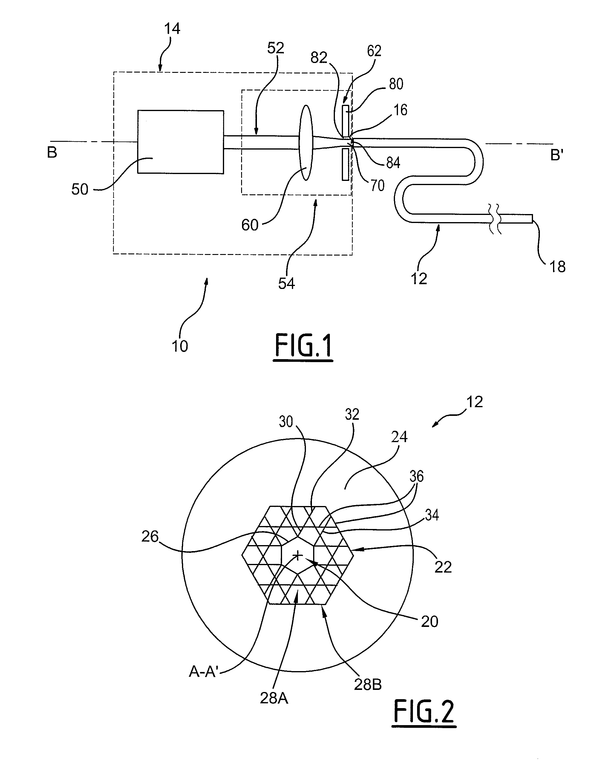
[0045]The device 10 is intended to generate and convey light pulses of high energy e.g. of energy higher than 1 microjoule, in particular higher than 1 millijoule. These pulses are intended to illuminate a sample for the conducting of spectroscopy, or are intended for the micro-machining of a part. These pulses can also be used for creating a spark intended to ignite a gas mixture present in an engine or turbine.

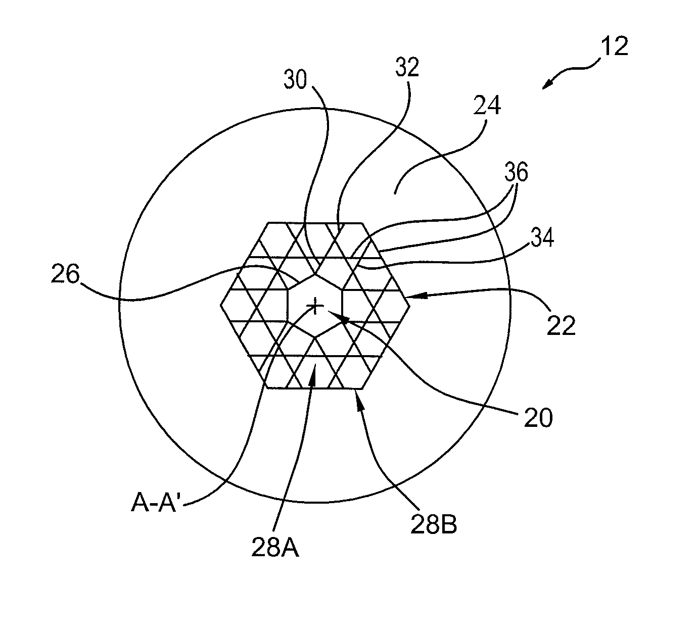
[0046]With reference to FIG. 1, the device 10 includes a hollow-core optical fiber 12 and an illuminating assembly 14 illuminating an upstream end 16 of the optical fiber 12.

[0047]According to the invention, the hollow-core optical fiber 12 forms an anti-resonant guide.

[0048]The guide is capable of con...


PUM


Abstract

A device is provided that includes an optical fiber and an assembly illuminating the optical fiber capable of illuminating the optical fiber at an upstream end. The optical fiber includes a hollow core and an anti-resonant annular cladding arranged around the hollow core. The illuminating assembly generates a focused beam of Airy spot shape for injection into the input of the optical fiber.

Description

[0001]The present invention concerns a device for transmitting light energy including[0002]a hollow-core optical fiber;[0003]an assembly for illuminating the optical fiber capable of illuminating the optical fiber at an upstream end.[0004]The device is intended to be used for micro-machining for example, for spectroscopy, for the laser ignition of engines and turbines or in other applications requiring the generating and conveying of a high energy light beam.BACKGROUND[0005]In all these fields, it is sometimes necessary to transmit short pulses through an optical fiber, for example lasting less than 100 nanoseconds, of high energy, for example of the order of one microjoule or millijoule.[0006]To do so, it is known to use multimodal optical fibers in silica.[0007]In this respect, and to avoid deterioration of the fiber, it is necessary to limit the transmitted energy taking into account the maximum acceptable power density in the core of the fiber.[0008]Beyond the damage threshold o...

Claims


Application Information

Patent Timeline
Patent Type & Authority Applications(United States)
IPC IPC(8): H01S3/30
CPCG02B6/4206G02B27/0927G02B27/0988G02B6/02347H01S3/005G02B6/4296G02B6/02328G02B27/46
Inventor GABOREL, GAELAUGUSTE, JEAN-LOUISHUMBERT, GEORGESGEROME, FREDERICBLONDY, JEAN-MARCBEAUDOU, BENOIT
Owner MEGGITT FRANCE
Why Eureka
Try Eureka