Image processing device and method

a processing device and image technology, applied in the field of image processing devices and methods, can solve the problems of unoptimized macroblock size of 1616 pixels, and achieve the effect of improving the encoding efficiency and improving the subjective image quality of decoded images

Inactive Publication Date: 2013-01-24
SONY CORP
View PDF6 Cites 15 Cited by
  • Summary
  • Abstract
  • Description
  • Claims
  • Application Information

AI Technical Summary

Benefits of technology

[0079]According to the present invention, encoding efficiency can be improved, and subjective image quality in decoded images can be improved.

Problems solved by technology

However, the macroblock size of 16×16 pixels is not optimal for large image frames such as UHD (Ultra High Definition; 4000×2000 pixels) which will be handled by next-generation encoding formats.

Method used


Image

  • Image processing device and method
  • Image processing device and method
  • Image processing device and method

Examples


Embodiment Construction

[0106]Hereinafter, embodiments of the present invention will be described with reference to the drawings.

[Configuration Example of Image Encoding Device]

[0107]FIG. 5 represents the configuration of an embodiment of an image encoding device serving as an image processing device to which the present invention has been applied.

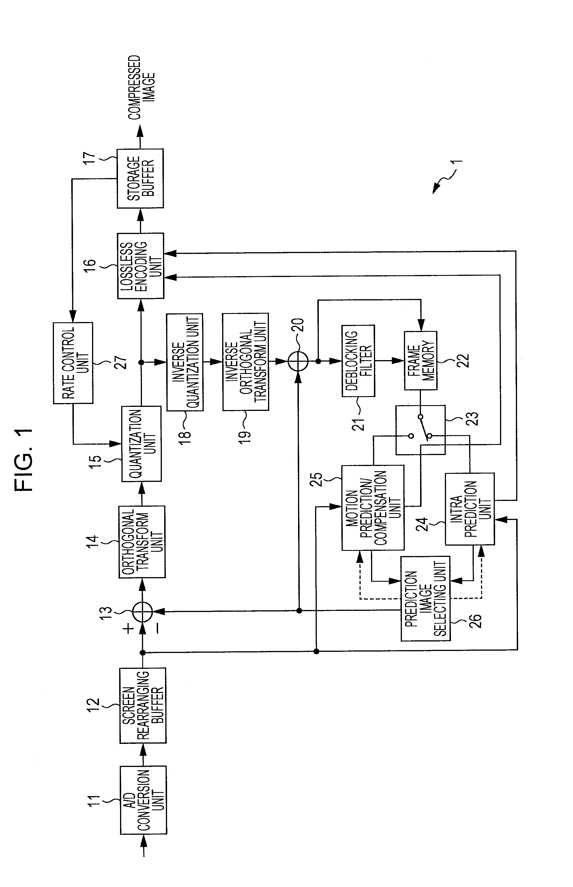
[0108]An image encoding device 101 in FIG. 5 is the same as the image encoding device 1 in FIG. 1 in that there are provided the A / D conversion unit 11, screen rearranging buffer 12, computing unit 13, orthogonal transform unit 14, quantization unit 15, lossless encoding unit 16, storage buffer 17, inverse quantization unit 18, inverse orthogonal transform unit 19, computing unit 20, deblocking filter 21, frame memory 22, switch 23, intra prediction unit 24, motion prediction / compensation unit 25, prediction image selecting unit 26, and rate control unit 27.

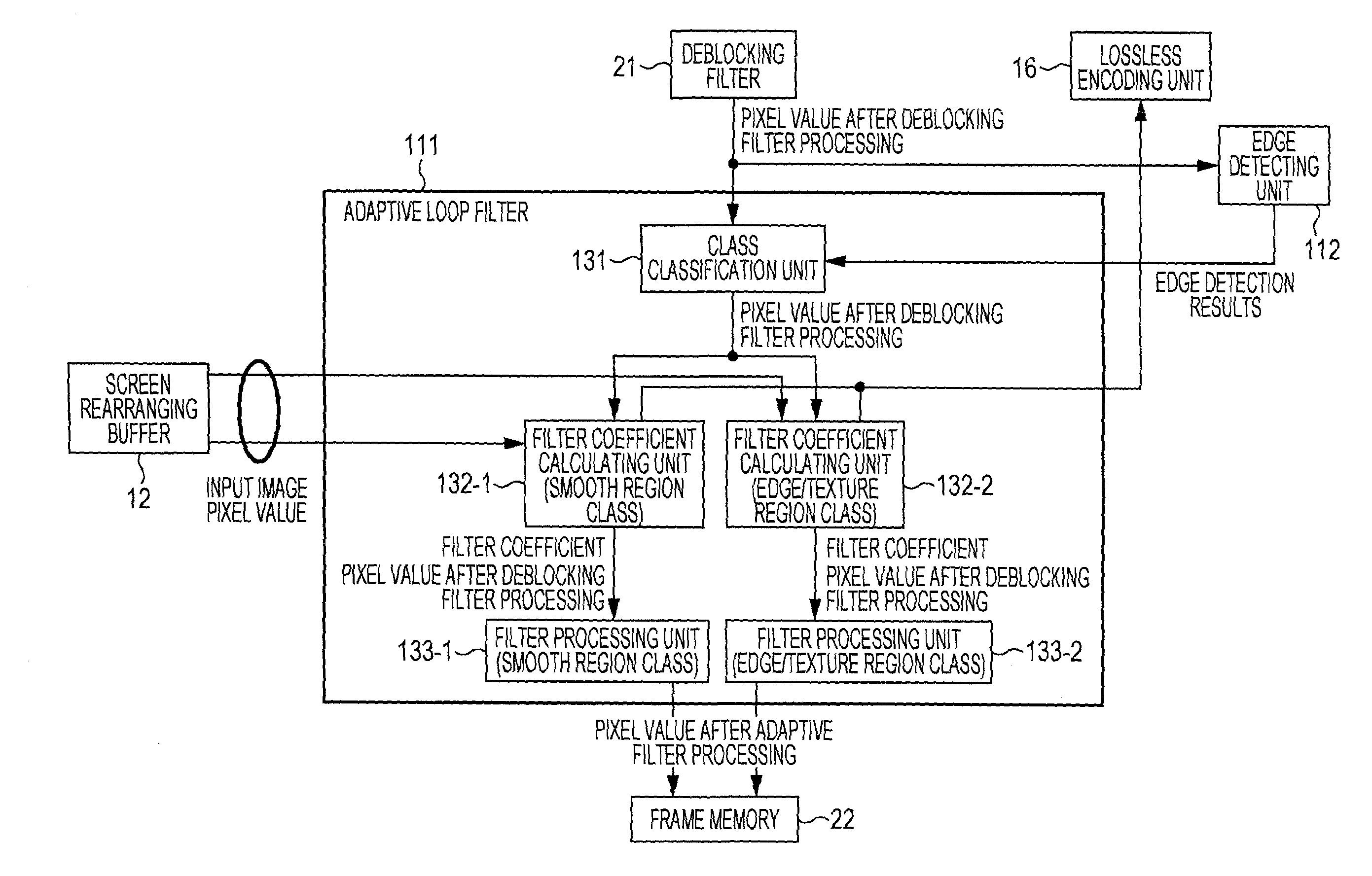
[0109]Also, the image encoding device 101 in FIG. 5 differs from the image encoding device 1 in FIG. 1 in t...


PUM


Abstract

An adaptive loop filter classifies a decoded image from a deblocking filter into a smooth region class and an edge/texture region class, in accordance with results of edge detection from an edge detecting unit. The adaptive loop filter performs filter coefficient calculation for each of classified classes such that the residual difference between an original image from a screen rearranging buffer and an image from the deblocking filter is smallest. The adaptive loop filter performs filter processing using filter coefficients calculated for each classified class, and outputs an image after filter processing to frame memory. The filter may be applied to an image encoding device for performing encoding with the H.264/AVC format as a basis, for example.

Description

TECHNICAL FIELD[0001]The present invention relates to an image processing device and method, and specifically relates to an image processing device and method which improves encoding efficiency and improves subjective image quality in decoded images.BACKGROUND ART[0002]In recent years, there have come into widespread use devices which subject an image to compression encoding by employing an encoding format handling image information as digital, and at this time compress the image by orthogonal transform such as discrete cosine transform or the like and motion compensation, taking advantage of redundancy peculiar to the image information, in order to perform highly effective information transmission and storage at that time. Examples of this encoding method include MPEG (Moving Picture Expert Group) and so forth.[0003]In particular, MPEG2 (ISO / IEC 13818-2) is defined as a general-purpose image encoding format, and is a standard encompassing both of interlaced scanning images and sequ...

Claims


Application Information

Patent Timeline
Patent Type & Authority Applications(United States)
IPC IPC(8): G06K9/62G06K9/40H04N19/102H04N19/00H04N19/117H04N19/136H04N19/14H04N19/176H04N19/19H04N19/196H04N19/503H04N19/593H04N19/61H04N19/625H04N19/82H04N19/86H04N19/91
CPCH04N19/82H04N19/176H04N19/14H04N19/172H04N19/61H04N19/117H04N19/182
Inventor SATO, KAZUSHI
Owner SONY CORP
Why Eureka
Try Eureka