Method and apparatus for polishing a substrate

Active Publication Date: 2013-01-24
EBARA CORP
View PDF2 Cites 46 Cited by
  • Summary
  • Abstract
  • Description
  • Claims
  • Application Information

AI Technical Summary

Benefits of technology

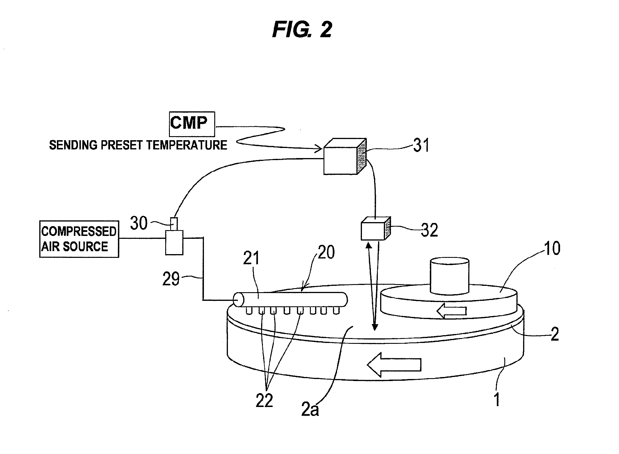
[0081]According to the present invention, the flow rate of the gas ejected from at least one gas ejection nozzle is controlled by the control valve and the temperature of the polishing pad is detected by the thermometer, and the flow rate of the gas ejected from at least one gas ejection nozzle can be controlled by comparing the preset temperature as a control target temperature of the polishing pad and the temperature of the polishing pad detected by the thermometer and by adjusting the ratio of valve opening of the control valve. Accordingly, the surface of the polishing pad can be controlled at the optimum temperature according to the CMP process.
[0082]In a preferred aspect of the present invention, the controller controls the flow rate of the gas ejected from at

Problems solved by technology

Therefore, there is a problem that mist of slurry supplied onto the polishing pad is scattered around.
Therefore, there is a problem that mist of pure water or the like sup

Method used


Image

  • Method and apparatus for polishing a substrate
  • Method and apparatus for polishing a substrate
  • Method and apparatus for polishing a substrate

Examples


first embodiment

[0123]A polishing apparatus and method according to the present invention will be described below with reference to FIGS. 1 through 9. Like or corresponding parts are denoted by like or corresponding reference numerals in FIGS. 1 through 9 and will not be described below repetitively.

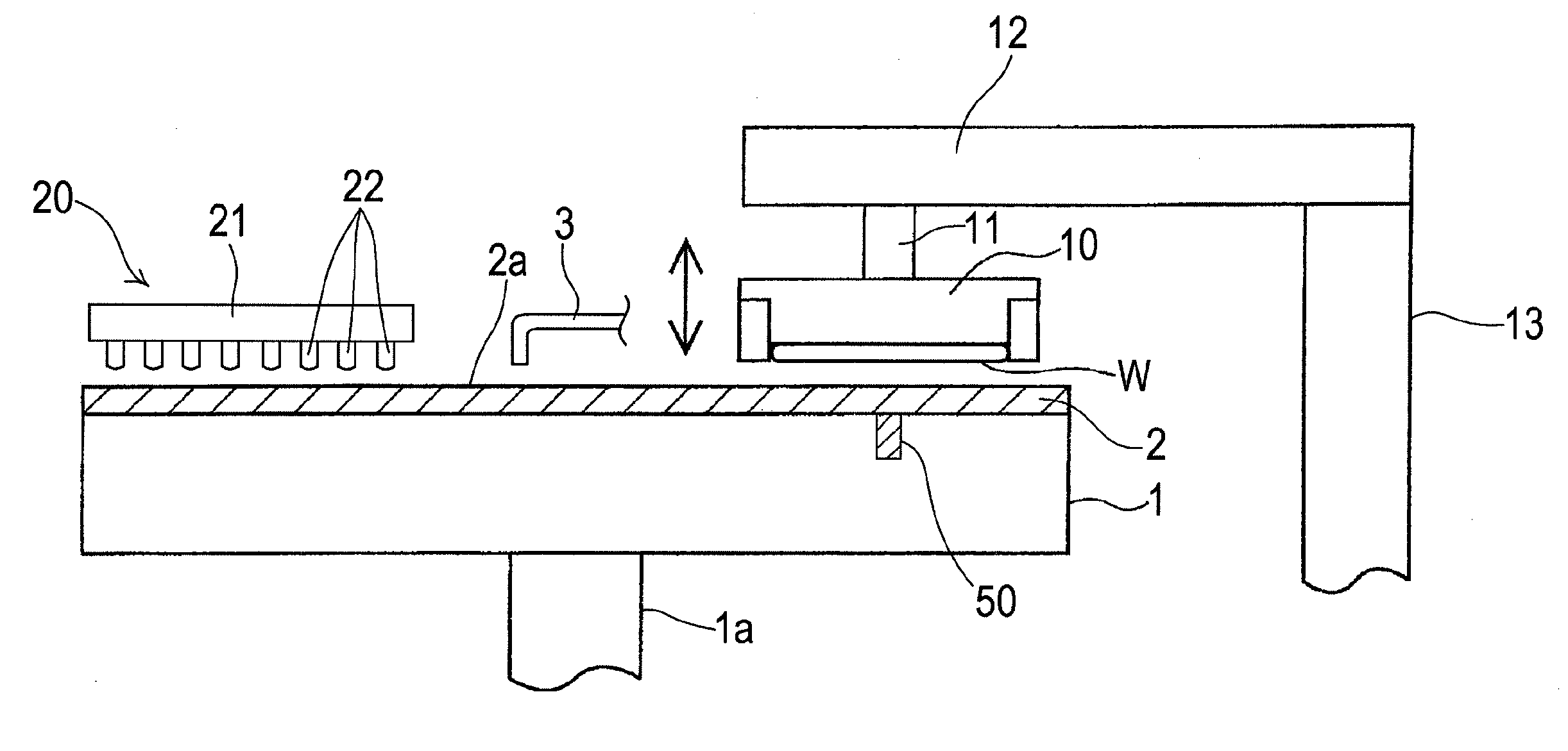
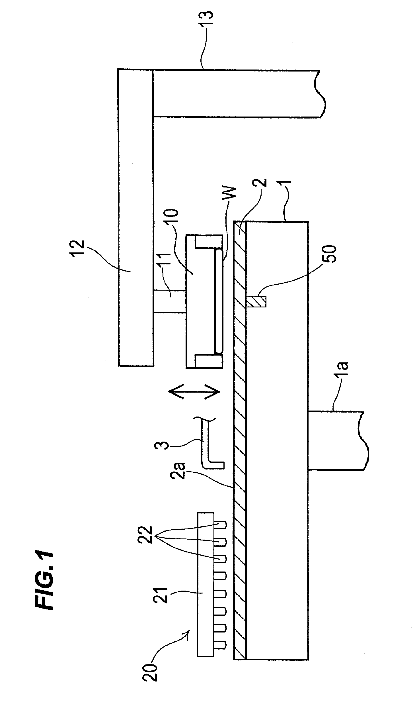
[0124]FIG. 1 is a schematic view showing an entire structure of a polishing apparatus according to a first embodiment of the present invention. As shown in FIG. 1, the polishing apparatus comprises a polishing table 1, and a polishing head 10 for holding a substrate W such as a semiconductor wafer as an object to be polished and pressing the substrate against a polishing pad on the polishing table 1. The polishing table 1 is coupled via a table shaft 1a to a polishing table rotating motor (not shown) disposed below the polishing table 1. Thus, the polishing table 1 is rotatable about the table shaft 1a. A polishing pad 2 is attached to an upper surface of the polishing table 1. An upper surface of the p...

second embodiment

[0157]A polishing apparatus and method according to the present invention will be described below with reference to FIGS. 10 through 29. Like or corresponding parts are denoted by like or corresponding reference numerals in FIGS. 10 through 29 and will not be described below repetitively.

[0158]FIG. 10 is a schematic perspective view showing an entire structure of a polishing apparatus according to a second embodiment of the present invention. As shown in FIG. 10, the polishing apparatus comprises a polishing table 101, and a top ring 110 for holding a substrate W such as a semiconductor wafer as an object to be polished and pressing the substrate against a polishing pad on the polishing table 101. The polishing table 101 is coupled via a table shaft to a polishing table rotating motor (not shown) disposed below the polishing table 101. Thus, the polishing table 101 is rotatable about the table shaft. A polishing pad 102 is attached to an upper surface of the polishing table 101. An ...


PUM

PropertyMeasurementUnit
Angleaaaaaaaaaa
Angleaaaaaaaaaa
Temperatureaaaaaaaaaa

Abstract

A polishing apparatus polishes a surface of a substrate by pressing the substrate against a polishing pad on a polishing table. The polishing apparatus is configured to control a temperature of the polishing surface of the polishing pad by blowing a gas on the polishing pad during polishing. The polishing apparatus includes a pad temperature control mechanism having at least one gas ejection nozzle for ejecting a gas toward the polishing pad and configured to blow the gas onto the polishing pad to control a temperature of the polishing pad, and an atomizer having at least one nozzle for ejecting a liquid or a mixed fluid of a gas and a liquid and configured to blow the liquid or the mixed fluid onto the polishing pad to remove foreign matters on the polishing pad. The pad temperature control mechanism and the atomizer are formed into an integral unit.

Description

CROSS REFERENCE TO RELATED APPLICATIONS[0001]This document claims priorities to Japanese Application Number 2011-158080, filed Jul. 19, 2011 and Japanese Application Number 2011-245482, filed Nov. 9, 2011, the entire contents of which are hereby incorporated by reference.BACKGROUND OF THE INVENTION[0002]1. Field of the Invention[0003]The present invention relates to a polishing apparatus and method for polishing a surface of a substrate such as a semiconductor wafer by relative movement between the surface of the substrate to be polished and a polishing pad on a polishing table while the substrate is pressed against the polishing pad, and more particularly to a polishing apparatus and method which can control a temperature of the surface (polishing surface) of the polishing pad by blowing a gas on the polishing pad.[0004]2. Description of the Related Art[0005]In recent years, high integration and high density in semiconductor device demands smaller and smaller wiring patterns or int...

Claims


Application Information

Patent Timeline
IPC IPC(8): B24B49/14B24B7/00B24B1/00B24B37/015
CPCB24B37/015B24B55/02B24B37/34B24B49/14B24B53/017
Inventor MOTOSHIMA, YASUYUKIMARUYAMA, TORUMATSUO, HISANORI
Owner EBARA CORP
Why Eureka
Try Eureka