
Motor-driven booster type brake system and method thereof

Active Publication Date: 2013-01-24
HYUNDAI MOBIS CO LTD
View PDF12 Cites 6 Cited by
  • Summary
  • Abstract
  • Description
  • Claims
  • Application Information

AI Technical Summary

Benefits of technology

The present patent is about a brake system for vehicles that prevents the brakes from locking up during sudden stops or turns. This system uses a motor to boost the brakes and stabilize the hydraulic pressure, reducing the chance of the brakes becoming too hot or too cold. This results in safer and more reliable braking performance for vehicles.

Problems solved by technology

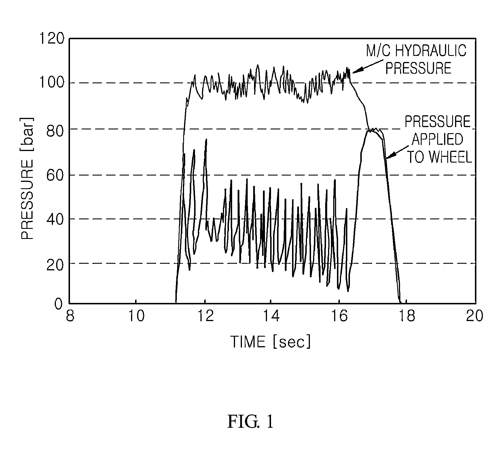
However, such a conventional motor-driven booster type brake system has a problem in that, when a vehicle is in an ABS mode, hydraulic pressure applied to the wheel brakes excessively increases or fluctuates in vehicle braking.
In this case, however, if some oil passages to the wheel brakes are repeatedly closed or opened in an ABS mode, it is difficult to achieve rapid change of hydraulic pressure output from the master cylinder to provide a suitable pedal force to the respective wheel brakes, casing excessive pressure to be applied to the wheel brakes.
Namely, since the conventional brake system simply compares an actual hydraulic pressure output from the master cylinder with a calculated target hydraulic pressure and changes the motor-driven type booster according to the result of comparison, the brake system cannot rapidly and effectively cope with variation of desired pedal force to be imparted to each of the wheel brakes according to operation of the ABS, so that excessive pedal force is imparted to the wheel brakes or fluctuation or divergence of braking pressure occurs, as indicated by a waveform shown at a lower part of FIG. 1.
Furthermore, such an excessive increase of hydraulic pressure can cause failure of the brake system.

Method used


Image

  • Motor-driven booster type brake system and method thereof
  • Motor-driven booster type brake system and method thereof
  • Motor-driven booster type brake system and method thereof

Examples


Embodiment Construction

[0022]Exemplary embodiments of the present disclosure will now be described in detail with reference to the accompanying drawings. It should be understood that these embodiments are provided for the purpose of illustration only and the scope of the present disclosure is not limited thereby.

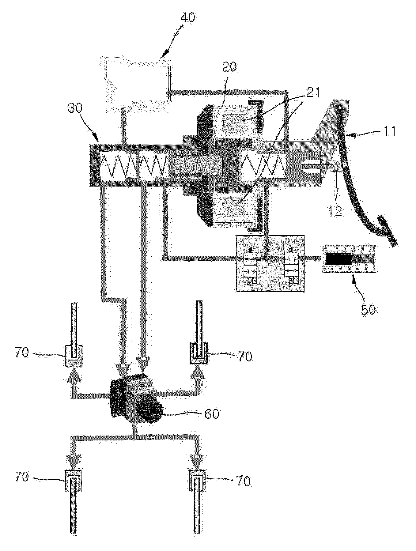
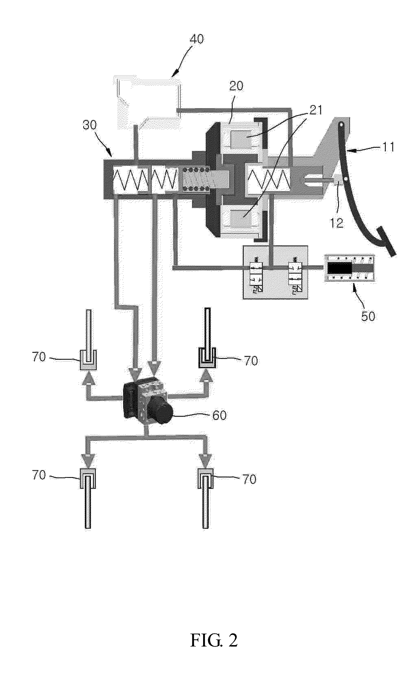
[0023]FIG. 2 is a schematic diagram of a motor-driven booster type brake system according to one exemplary embodiment, FIG. 3 is a flowchart of a braking method of a motor-driven booster type brake system according to one exemplary embodiment, and FIG. 4 is a graph depicting variation of input electric current applied to a motor included in the booster in an ABS mode, according to the exemplary embodiment.

[0024]Referring to FIGS. 2 to 4, exemplary embodiments will be described.

[0025]In FIG. 2, a motor-driven booster type brake system according to one exemplary embodiment includes a pedal force sensor 12 for sensing a detecting pedal force of a driver pressing on a brake pedal; a master cylinder 30...


PUM


Abstract

The present disclosure provides a motor-driven booster type brake system and method thereof. The brake system includes a pedal force sensor for detecting pedal force of a driver applied to a brake pedal, a master cylinder delivering hydraulic pressure to wheel brakes, a booster delivering multiplied force to the master cylinder using a motor, and an ECU controlling the motor based on a detection value of the pedal force. In the brake system, the ECU controls the motor based on hydraulic pressure delivered from the master cylinder to the wheel brakes if an ABS mode is not activated, and controls the motor by maintaining an electric current input to the motor to be within a preset range of electric current if the ABS mode is activated.

Description

CROSS-REFERENCE TO RELATED APPLICATION[0001]This application claims the benefit under 35 U.S.C. §119 of Korean Patent Application No. 10-2011-0073264, filed Jul. 22, 2011, which is hereby incorporated by reference in its entirety.BACKGROUND[0002]1. Technical Field[0003]The present disclosure generally relates to a motor-driven booster type brake system and method thereof. More particularly, the present disclosure relates to a motor-driven booster type brake system and method thereof, which is configured to generate hydraulic pressure in a master cylinder through multiplication of force using a motor of a motor-driven booster to achieve vehicle braking[0004]2. Description of the Related Art[0005]The background art of the present disclosure is disclosed in Korean Patent Laid-open Publication No. 2010-0098847 (Laid-open Date: Sep. 10, 2010).[0006]Typically, in a motor-driven booster type brake system, when a driver presses on a brake pedal, a pedal force sensor detects pedal force of t...

Claims


Application Information

Patent Timeline
IPC IPC(8): B60T8/172
CPCB60T7/042B60T8/3265B60T8/4077B60T8/176B60T8/4836B60T2270/14B60T13/745B60T8/17B60T13/74
Inventor JUNG, WAN KYO
Owner HYUNDAI MOBIS CO LTD
Learn More