Eureka AIR delivers breakthrough ideas for toughest innovation challenges, trusted by R&D personnel around the world.

Excavator and process for assembling or dissassembling such excavator

a technology for excavators and hydraulic circuits, applied in fluidic programme control, program control, instruments, etc., can solve the problems of not being able to test the hydraulic pilot circuit, the hydraulic circuit is not able to be operated for diagnosing purposes, and the connection of controllers is often quite complicated, so as to achieve the effect of facilitating assembly and disassembly of the hydraulic circuit assembly

Active Publication Date: 2013-01-31
VOLVO COMPACT EQUIP
View PDF7 Cites 7 Cited by
  • Summary
  • Abstract
  • Description
  • Claims
  • Application Information

AI Technical Summary

Benefits of technology

The invention is about hydraulic excavators or mini-excavators with hydraulically operated tools. The technical effect of the patent is to provide a rotary joint that allows hydraulic lines to pass from the upper frame to the lower frame without being interrupted, and without impeding the free swiveling of the two frames. This allows for more flexible and efficient operation of the machine's tools.

Problems solved by technology

For example, it is frequently quite complicated to perform such connection of the controllers, because of lack of accessibility.
Also, such assembly process makes it impossible to test the hydraulic pilot circuit, for example for leaks, before the assembly of the platform.
If an hydraulic component is found to be defective, it may be necessary to disassemble the platform to provide some remedy, but such disassembly of the platform necessitates a prior disconnection of the pilot circuit from the hydraulic distribution system so that it is not any more possible to operate the hydraulic circuit for diagnosing purposes.

Method used


Image

  • Excavator and process for assembling or dissassembling such excavator
  • Excavator and process for assembling or dissassembling such excavator
  • Excavator and process for assembling or dissassembling such excavator

Examples


Embodiment Construction

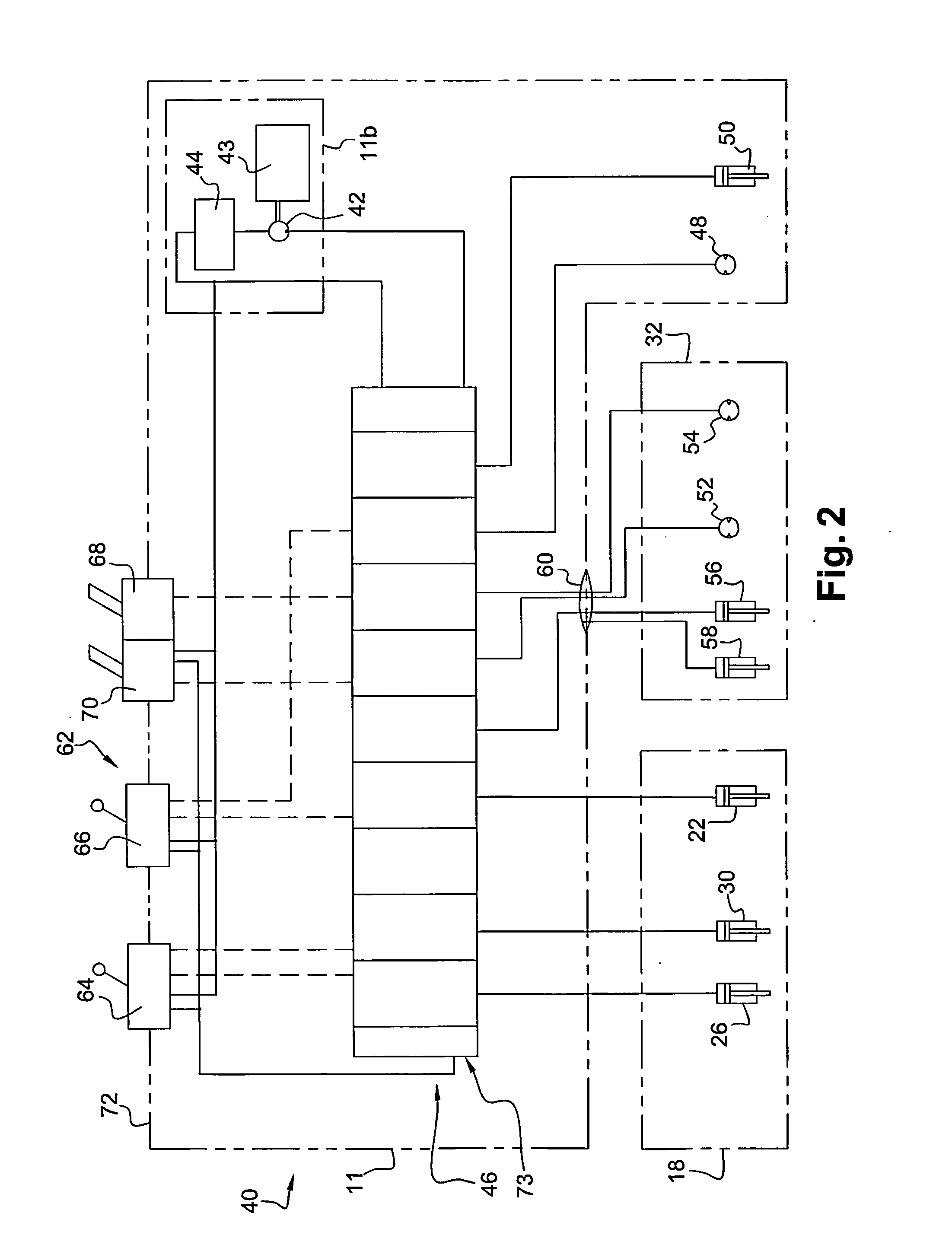
[0038]On FIG. 2 are represented most components of a hydraulic circuit assembly 40 for an excavator 10. This circuit assembly is conventional and well known to the skilled man in the art. In FIG. 2, hydraulic connections are symbolically represented and the number of pipes necessary for such connections is not shown.

[0039]The circuit assembly 40 comprises a main pump 42, which is driven by the engine arrangement, such as a Diesel engine 43, and which takes oil from a hydraulic oil tank 44 to pressurize it and deliver it to a hydraulic distribution system 46. Various additional components such as oil filters, oil coolers, pressure regulators, safety valves may be provided in a conventional way. The hydraulic distribution system 46 may be connected to the hydraulic oil tank 44 by a main return line 45.

[0040]The hydraulic distribution system 46 distributes the pressurized fluid from the main pump to various hydraulic actuators. These actuators may include the cylinders 22, 26, 30 of th...


PUM

PropertyMeasurementUnit
weightaaaaaaaaaa
pressureaaaaaaaaaa
flow rateaaaaaaaaaa

Abstract

An excavator includes a frame, and a platform on top of the frame. A hydraulic distribution system is received on top of the frame but below the platform. A pilot valve unit is at least partly received on top of the platform. The platform includes a dedicated hole capable of receiving therethrough at least that part of the pilot valve unit which is received on top of the platform. The pilot valve unit is fixed, directly or indirectly, on the platform. The pilot valve unit can be mounted from below the platform, through the dedicated hole, and is fixed on the platform from above the platform.

Description

BACKGROUND AND SUMMARY[0001]The invention relates to the field hydraulic excavators or mini-excavators having hydraulically operated earth-moving tools.[0002]On FIG. 1 is depicted a conventional excavator 10. It comprises an upper frame 11 carrying the excavator's superstructure 12 which comprises an operator station which can be enclosed in a closed cabin 14 and an engine arrangement which may be located in a rearwardly located engine compartment 16. Some excavators do not have such closed cabin and have an operator station which can be totally open or only covered by a canopy. The upper frame carries the machine's main work equipment: a digging assembly 18. Typically, the digging assembly 18 can have a boom 20 which is pivotably connected around a horizontal axis on the upper frame. The boom 20 can be lowered and lifted vertically by a boom cylinder 22. At the free end of the boom 20, an arm 24 may be pivotably connected around another horizontal axis, and it can be lowered and li...

Claims


Application Information

Patent Timeline
Patent Type & Authority Applications(United States)
IPC IPC(8): E02F9/22B23P11/00
CPCE02F9/08E02F9/2004E02F9/2267Y10T29/49826E02F9/2275E02F9/2285E02F9/2271
Inventor CAILLIERET, ROGERARNAL, GREGORY
Owner VOLVO COMPACT EQUIP
Why Eureka
Eureka Blog
Learn More