Ducted fan gas turbine assembly

a technology of gas turbine and aft cowl, which is applied in the direction of machines/engines, climate sustainability, sustainable transportation, etc., can solve the problems of large increase in the discharge area of the nozzle, the need for aft cowl translation a relatively long distance, and the actuation mechanism for the translation of the cowl

Active Publication Date: 2013-01-31
ROLLS ROYCE PLC
View PDF3 Cites 39 Cited by
  • Summary
  • Abstract
  • Description
  • Claims
  • Application Information

AI Technical Summary

Benefits of technology

[0009]It would be desirable to provide a combined thrust reverser and variable area nozzle which can overcome some or all of these disadvantages.

Problems solved by technology

Further rearward translation, however, exposes cascade turning vanes and causes deployment of blocker doors to produce reverse thrust.
A disadvantage, however, of the proposal of U.S. Pat. No. 5,655,360 is that to produce large increases in the discharge area of the nozzle it is necessary for the aft cowl to be translated a relatively long distance.
This complicates both the actuation mechanism for the cowl translation, and also the actuation mechanism for deployment of the blocker doors which must only be deployed when further rearward translation exposes the cascade turning vanes.
A further disadvantage of this arrangement is that a single actuator varies the area of the discharge nozzle, and provides thrust reversal.
Such a system poses a risk that the thrust reverser could deploy in flight, which may lead to the loss of the aircraft.
Complex safety systems would therefore be required, further complicating the design.

Method used


Image

  • Ducted fan gas turbine assembly
  • Ducted fan gas turbine assembly
  • Ducted fan gas turbine assembly

Examples


Embodiment Construction

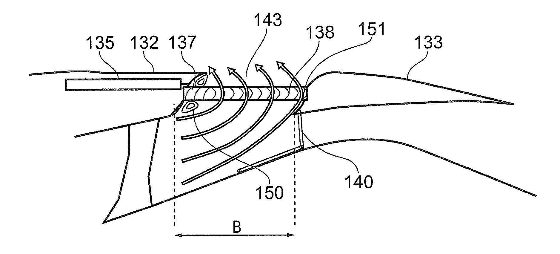
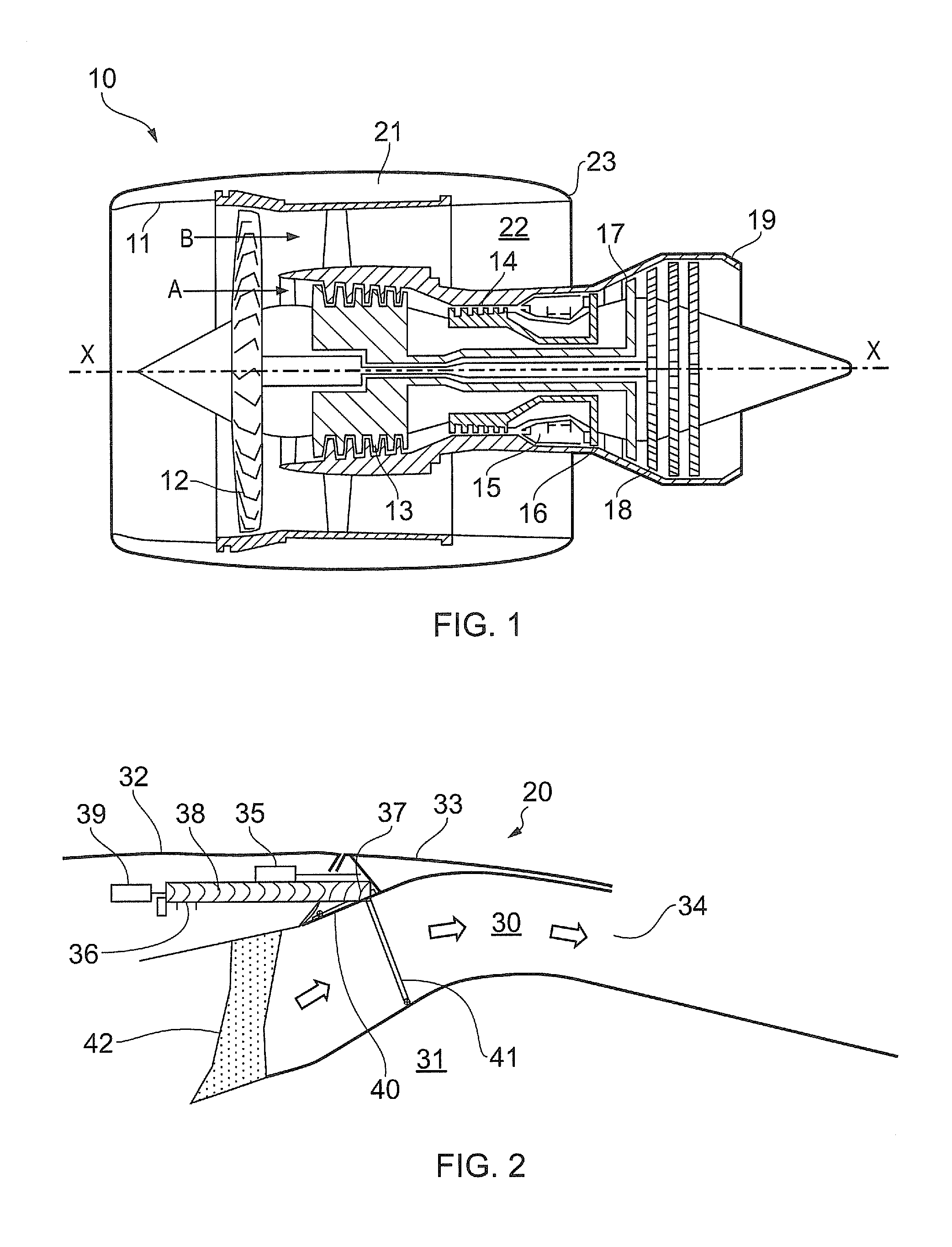
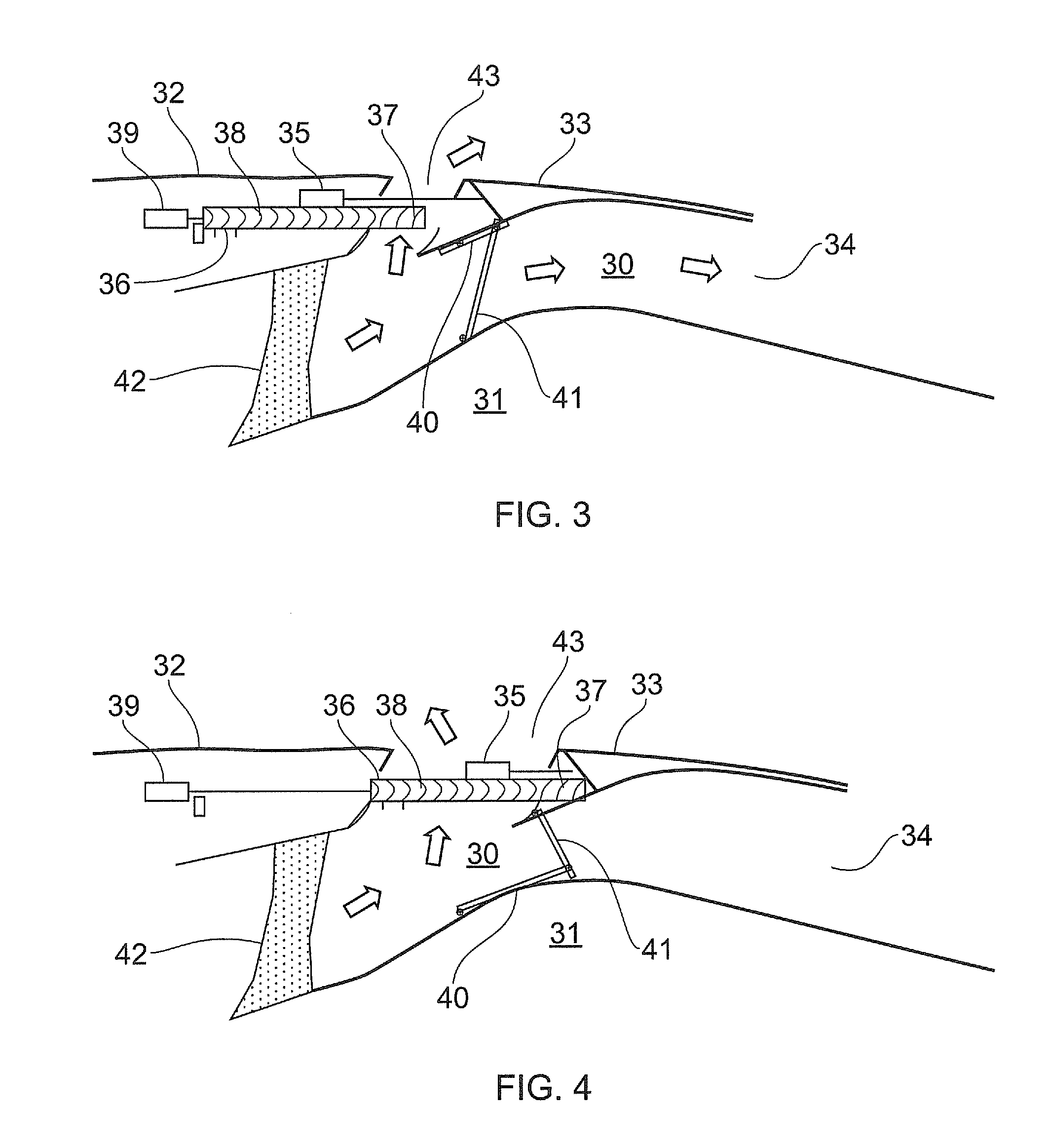
[0037]FIG. 2 shows a schematic longitudinal section through a first thrust reverser assembly 20 in a first operational configuration. An annular bypass duct 30 receives an airflow (arrowed) from a propulsive fan (not shown) of a turbofan engine. The duct is formed between a core engine 31 and a nacelle and terminates in a primary discharge nozzle 34. The nacelle has a stationary cowl portion 32 and a movable cowl portion 33 which is translatable rearwardly relative to the stationary cowl portion. Typically, the movable cowl portion is formed as left engine side and right engine side half-cowls, which split apart about a vertical plane through the engine axis when moved rearwardly. Each half-cowl can be moved rearwardly by one or more first actuators 35 (only one shown in FIG. 2). Typically, there are at least two such actuators per half-cowl. In this embodiment, the first and second actuators 35, 39 are hydraulic actuators. However, electric or pneumatic actuators could be used.

[003...


PUM


Abstract

A ducted fan gas turbine assembly has a propulsive fan driven by a core engine. The turbine assembly has an annular bypass duct which receives an airflow from the fan and is bounded on the radially inward side by the core engine and on the radially outward side by an engine nacelle. The turbine assembly has a thrust reverser assembly having a vane arrangement including a first set of turning vanes for channelling airflow from the duct in a rearward direction, a second set of turning vanes for channelling airflow from the bypass duct in a forward direction. The thrust reverser assembly includes a plurality of blocker doors which are deployable to block the bypass duct. The nacelle has stationary and movable cowl portions that cooperate with the thrust reverser assembly to provide several operational configurations.

Description

FIELD OF THE INVENTION[0001]The present invention relates to a ducted fan gas turbine assembly.BACKGROUND OF THE INVENTION[0002]With reference to FIG. 1, a ducted fan gas turbine engine generally indicated at 10 has a principal and rotational axis X-X. The engine comprises, in axial flow series, an air intake 11, a propulsive fan 12, and a core engine including an intermediate pressure compressor 13, a high-pressure compressor 14, combustion equipment 15, a high-pressure turbine 16, and intermediate pressure turbine 17, a low-pressure turbine 18 and a core engine exhaust nozzle 19. A nacelle 21 generally surrounds the engine 10 and defines the intake 11, a bypass duct 22 and a bypass exhaust nozzle 23.[0003]The gas turbine engine 10 works in a conventional manner so that air entering the intake 11 is accelerated by the fan 12 to produce two air flows: a first air flow A into the core engine and a second air flow B which passes through the bypass duct 22 to provide propulsive thrust....

Claims


Application Information

Patent Timeline
Patent Type & Authority Applications(United States)
IPC IPC(8): F02K1/68
CPCF02K1/72Y02T50/671F02K3/075F02K1/09Y02T50/60
Inventor BEARDSLEY, PETER K.BOLGAR, CRISPIN D.
Owner ROLLS ROYCE PLC
Why Eureka
Try Eureka