Label dispensing device and method

Active Publication Date: 2013-01-31
BRADY WORLDWIDE INC
View PDF1 Cites 2 Cited by
  • Summary
  • Abstract
  • Description
  • Claims
  • Application Information

AI Technical Summary

Benefits of technology

[0010]The disclosed apparatus permits a wider range of materials (e.g., of various thicknesses, stiffnesses, etc.) to be used in a label dispensing apparatus with an aggressive rake angle without so severely limiting the spacing between the labels on the web or liner. By including a transition member below the beak or dispensing member, the distance between the print head and peel edge of the dispensing member can be reduced in comparison to a dispensing member having an equal rake angle with no transition member. The peel edge of dispensing member without a corresponding transition member would need be extended further forward in order to avoid interference with the platen if the return path was initially linear. Because the labels can be placed closer together on the web, the amount of backfeeding can be reduced or eliminated altogether and/or the amount of scrap material from the web may be reduced. Additionally, the web can return from a bent or folded configuration at the peel edge of the dispensing member to a planar configura

Problems solved by technology

Unfortunately, this meant that to avoid back feeding of the web during printing and dispensing, the spacing between the labels on the web would need to be increased such that the spacing between l

Method used


Image

  • Label dispensing device and method
  • Label dispensing device and method
  • Label dispensing device and method

Examples


Embodiment Construction

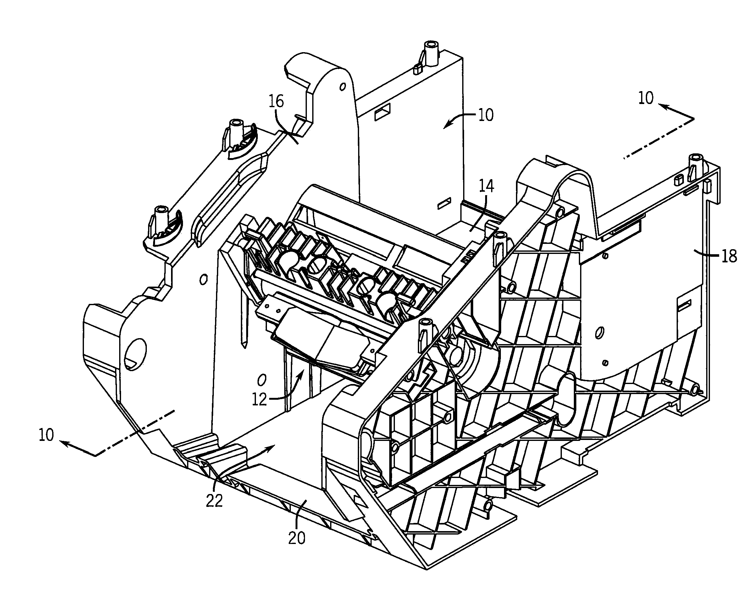
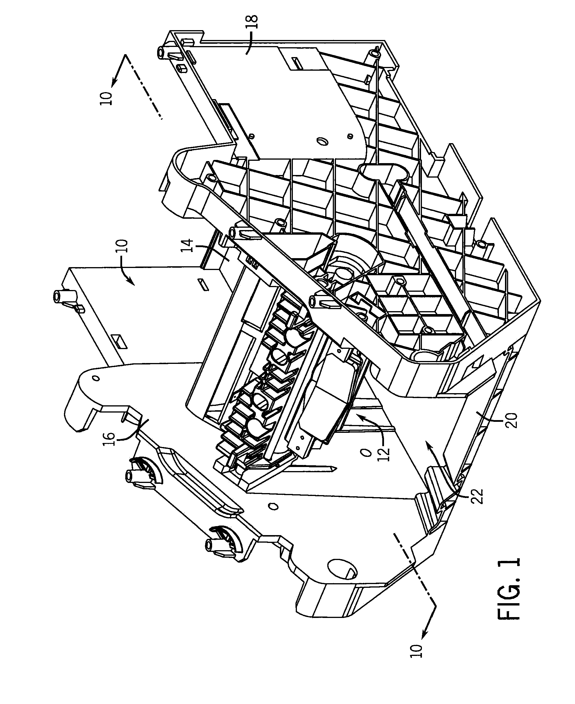
[0027]Referring first to FIG. 1, a portion of a printer is shown for printing of labels on a continuous liner or web (not depicted in FIG. 1, but shown in the cross-section of FIG. 10) and for subsequently separating the printed labels from the liner. The printed labels are separated from the liner by bending the web in a direction transverse to the direction of travel of the web path and then turning the web over a peel edge such that the label, which is more rigid than the liner when bent in the transverse direction, continues forward and separates from the liner while the liner is turned back.

[0028]As shown in FIG. 1, the illustrated portion of the printer includes a housing 10 that supports a label dispensing device 12. The housing 10 and the label dispensing device 12 are typically received in a larger housing or a case that includes not only the illustrated components, but also other components such as, for example, components that support a supply of the web (e.g., a roll or ...


PUM

PropertyMeasurementUnit
Lengthaaaaaaaaaa
Angleaaaaaaaaaa
Radiusaaaaaaaaaa

Abstract

A label dispensing device is disclosed for dispensing labels from a web that has a web path extending through the label dispensing device. The label dispensing device includes a dispensing member and a transition member. The dispensing member is shaped to effectuate a flexure of the web and includes a peel edge disposed along a portion of the web path. The transition member has a web control surface disposed along a portion of the web path. The web control surface is downstream of the peel edge and is configured to engage the first side of the web, thereby reducing the flexure of the web effectuated by the dispensing member.

Description

CROSS-REFERENCE TO RELATED APPLICATIONS[0001]Not applicable.STATEMENT OF FEDERALLY SPONSORED RESEARCH OR DEVELOPMENT[0002]Not applicable.BACKGROUND[0003]This disclosure relates to label dispensing devices and related methods of use. In particular, this disclosure relates to devices for the dispensing of labels carried on a liner or web.[0004]Label printers are commonly used to print text, barcodes, and other images. For such label printers, labels are usually provided on a release liner from which the labels can be separated. Typically, a web is fed through the printer with the labels on the liner and, after printing, the printed label may be removed from the web and applied to an item.[0005]Many label printers require that, after the label has been printed, a user manually remove the printed label from the web and then apply the printed label to an object. However, to facilitate efficiency in high-throughput working environments, some printers have been designed to perform some of ...

Claims


Application Information

Patent Timeline
IPC IPC(8): B32B38/10B65C9/08B65C9/00
CPCB65C9/0006Y10T156/1978Y10T156/1994Y10T156/19Y10T156/1195Y10T156/11Y10T156/16Y10T156/17
Inventor ANWAR, SOHAILHARTMANN, PETER
Owner BRADY WORLDWIDE INC
Why Eureka
Try Eureka