Motor drive apparatus
- Summary
- Abstract
- Description
- Claims
- Application Information
AI Technical Summary
Benefits of technology
Problems solved by technology
Method used
Image
Examples
embodiment 1
1. Embodiment 1
Configuration
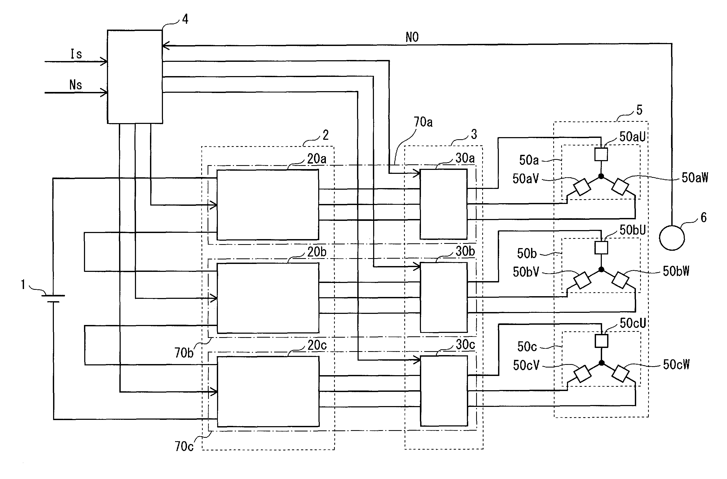
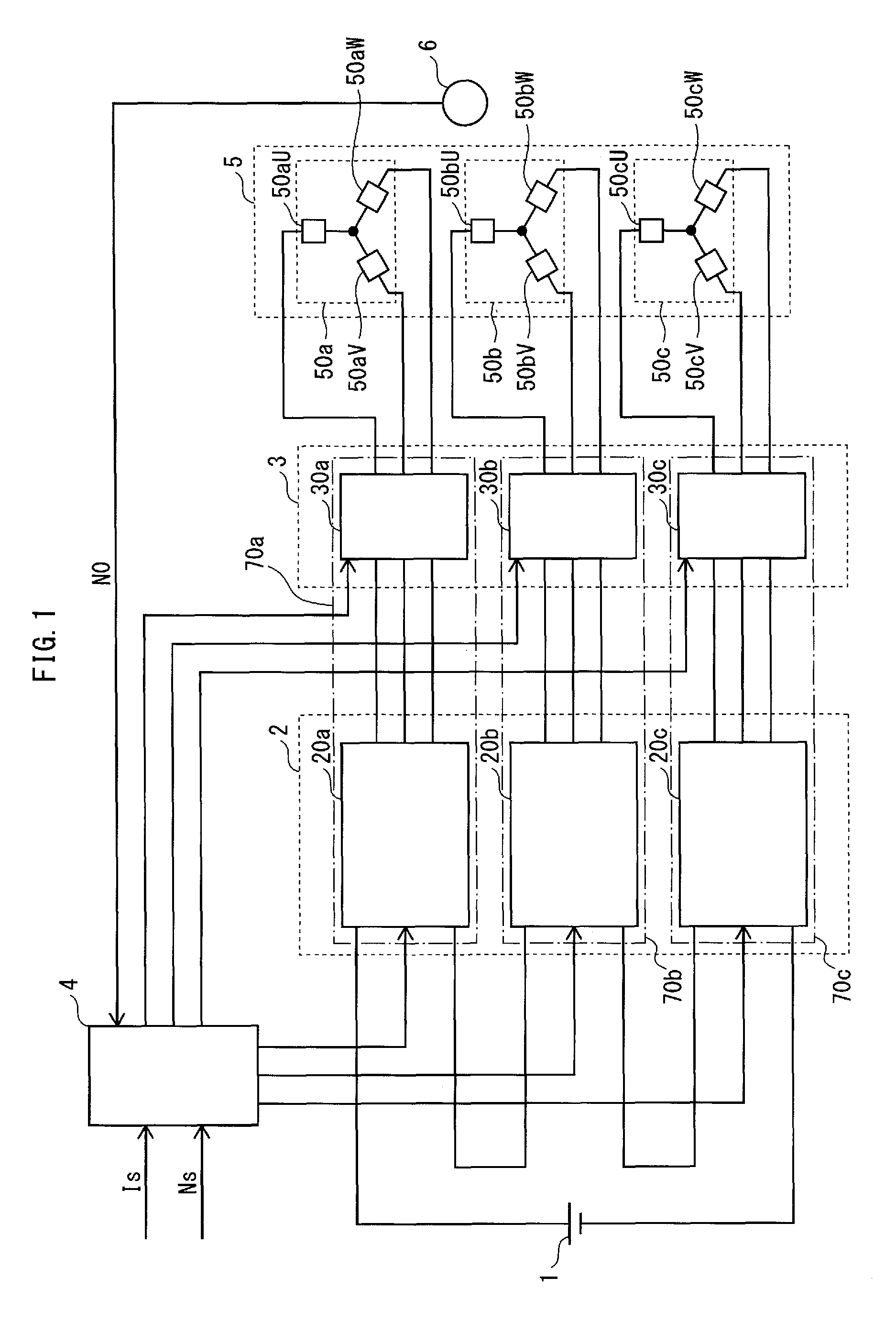
[0055]FIG. 1 illustrates the overall configuration of a motor drive apparatus pertaining to Embodiment 1.
[0056]The motor drive apparatus includes an inverter circuit group 2, an interrupter circuit group 3, a control circuit 4, and a position detector 6, and is connected to a DC power source 1 and to a motor 5.
[0057]The DC power source 1 supplies DC power to the inverter circuit group 2.
[0058]The inverter circuit group 2 includes three-phase inverter circuits 20a, 20b, and 20c. Three-phase inverter circuit 20a is a three-phase bridge inverter circuit providing a bridge between six switching elements.
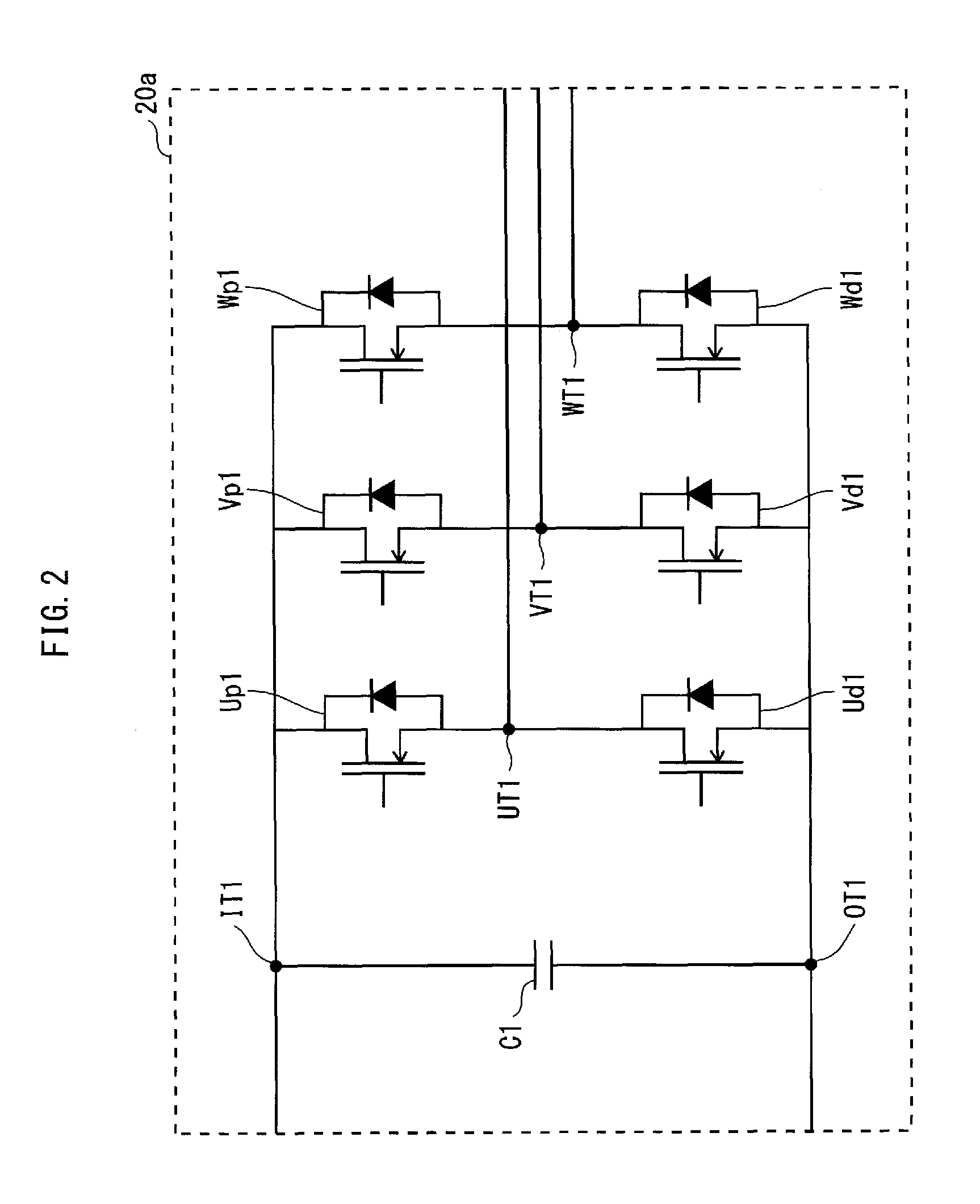
[0059]FIG. 2 is a circuit diagram illustrating the details of three-phase inverter circuit 20a.
[0060]As shown in FIG. 2, three-phase inverter circuit 20a includes switching elements Up1 and Ud1, Vp1 and Vd1, and Wp1 and Wd1, respectively connected in series. These serially-connected switching elements are connected in parallel to a smoothing capacitor C1. Th...
embodiment 2
2. Embodiment 2
[0084]In the present Embodiment, the temperature of the power converter is detected in order to avoid abnormal states and damage caused by excessively high power converter temperatures, thus enabling improvements in the useful life of the power converter and enhancing the overall reliability of the motor drive apparatus.
[0085]FIG. 10 illustrates the overall configuration of a motor drive apparatus pertaining to Embodiment 2.
[0086]In the motor drive apparatus illustrated in FIG. 10, the inverter circuit group 2, the power converters 70a through 70c, and the control circuit 4 of the motor drive apparatus from FIG. 1 are respectively replaced by inverter circuit group 200, power converters 71a through 71c, and control circuit 400.
[0087]The inverter circuit group 200 includes the three-phase inverter circuits 21a, 21b, and 21c.
[0088]FIG. 11 is a circuit diagram illustrating the details of three-phase inverter circuit 21a.
[0089]Three-phase inverter circuit 21a is configu...
embodiment 3
3. Embodiment 3
[0096]In Embodiment 2, the temperature of the switching element is detected to detect the power converter temperature. However, in the present Embodiment, the temperature of the smoothing capacitor is detected to detect the power converter temperature.
[0097]FIG. 13 illustrates the overall configuration of a motor drive apparatus pertaining to Embodiment 3.
[0098]In the motor drive apparatus illustrated in FIG. 13, the inverter circuit group 2, the power converters 70a through 70c, and the control circuit 4 of the motor drive apparatus from FIG. 1 are respectively replaced by inverter circuit group 201, power converters 72a through 72c, and control circuit 401.
[0099]The inverter circuit group 201 includes three-phase inverter circuits 22a, 22b, and 22c. Power converter 72a includes three-phase inverter circuit 22a and interrupter circuit 30a, power converter 72b includes three-phase inverter circuit 22b and interrupter circuit 30b, and power converter 72c includes three...
PUM
 Abstract
Description
Claims
Application Information
 - R&D
- Intellectual Property
- Life Sciences
- Materials
- Tech Scout
- Unparalleled Data Quality
- Higher Quality Content
- 60% Fewer Hallucinations
Browse by: Latest US Patents, China's latest patents, Technical Efficacy Thesaurus, Application Domain, Technology Topic, Popular Technical Reports.
© 2025 PatSnap. All rights reserved.Legal|Privacy policy|Modern Slavery Act Transparency Statement|Sitemap|About US| Contact US: help@patsnap.com


