
Liquid DIMM cooling device

a cooling device and liquid dimming technology, applied in the direction of electrical apparatus casings/cabinets/drawers, semiconductor/solid-state device details, instruments, etc., can solve the problems of consuming a considerable amount of space, unable to adequately cool microelectronic components, and difficult to implement using air flow cooling

Active Publication Date: 2013-01-31
IBM CORP
View PDF31 Cites 33 Cited by
  • Summary
  • Abstract
  • Description
  • Claims
  • Application Information

AI Technical Summary

Benefits of technology

The patent text discusses the problem of microelectronic components, such as memory modules, generating too much heat during operation and the need for effective cooling to ensure reliable performance and a long lifetime. In the past, air cooling has been used but it has been found to be inadequate, especially for densely packed components like DIMMs. The technical effect of the patent is to provide a powerful cooling system for microelectronic components.

Problems solved by technology

However, these air cooling arrangements have been found to consume a considerable amount of space and / or fail to adequately cool the microelectronic components.
Due to the high density and close vicinity of powerful memory modules on the circuit board, DIMMs need reliable and highly effective cooling which is difficult to implement using air flow cooling.

Method used


Image

  • Liquid DIMM cooling device
  • Liquid DIMM cooling device
  • Liquid DIMM cooling device

Examples


Embodiment Construction

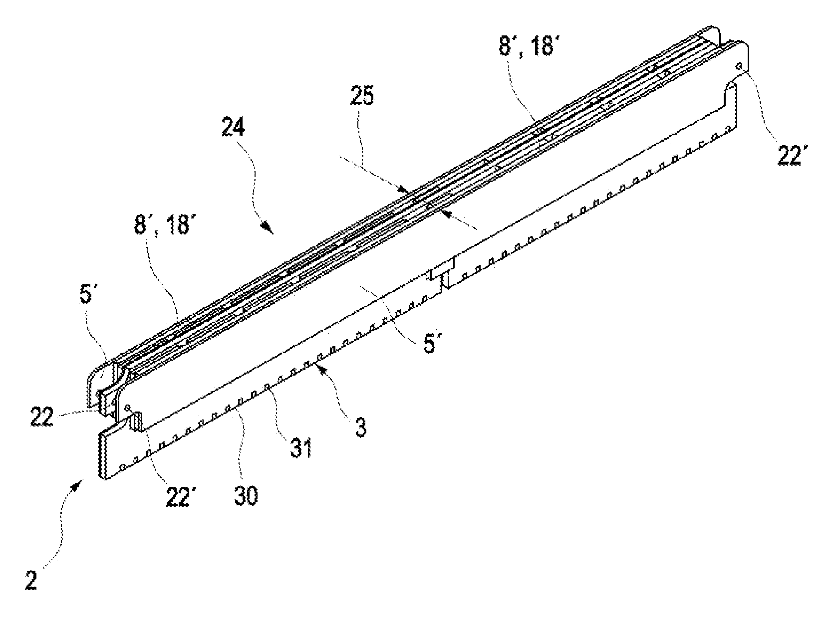
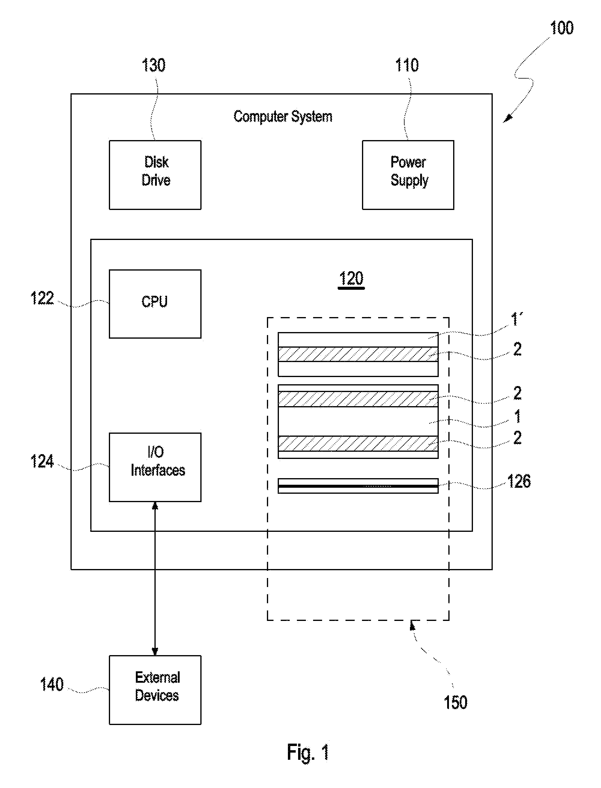
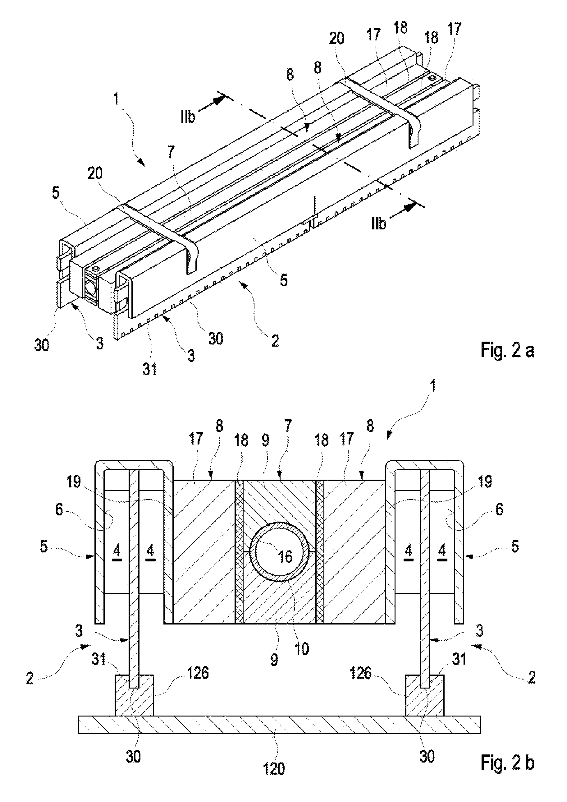
[0014]One embodiment of the present invention provides a liquid cooling device comprising a heat spreader disposed along the plurality of memory modules on a dual in-line memory module, a cold rail block extending along the heat spreader and a compressible thermal adapter interleaved between the cold rail block and the memory modules of the DIMM.

[0015]The compressibility of the thermal adapter interleaved between the cold rail and the DIMM allows the components of the cooling device to be moved and adjusted relative to each other in a direction perpendicular to the plane of the DIMM's circuit boards. The compressible adapter thus acts like a spring which holds the components in place and assures good mechanical and thermal contact. The compressible adapter thus compensates dimensional differences and inaccuracies of the various components of the liquid cooling device. By manually compressing the adapter, the DIMM may be removed from the cooling device. In a preferred embodiment, sel...


PUM


Abstract

A liquid cooling device comprises a heat spreader disposed along a plurality of memory modules on a dual in-line memory module (DIMM), a cold rail block extending along the heat spreader and a compressible thermal adapter interleaved between the cold rail block and the memory modules. The thermal adapter is compressible in a direction perpendicular to the plane of the DIMM board, thus allowing the components of the cooling device to be moved and adjusted relative to each other in a direction perpendicular to the plane of the DIMM. In a preferred embodiment, matching smooth surfaces of adjacent components within the cooling device are collated with a lubricant, thus permitting a low-friction gliding of these components relative to each other and allowing the DIMM to be easily removed from the cooling device and to be replaced without effort and without tooling.

Description

BACKGROUND[0001]1. Field of the Invention[0002]The present invention relates generally to cooling of electronic components, and specifically to a liquid cooling device for electronic circuit boards.[0003]2. Background of the Related Art[0004]Microelectronic components such as memory modules contained in computers and electronic devices generate substantial amounts of heat during operation which must be removed in order to ensure reliable performance and a long lifetime of the components. In the past, this has been achieved by using air cooling, for example with fans forcing an air flow through the electronic device. However, these air cooling arrangements have been found to consume a considerable amount of space and / or fail to adequately cool the microelectronic components. In particular, usage of densely packed powerful microelectronic components such as dual in-line memory modules (DIMMs) requires a powerful cooling system.[0005]A DIMM is a narrow elongated electronic circuit boar...

Claims


Application Information

Patent Timeline
IPC IPC(8): G06F1/20
CPCH01L23/473H01L2924/0002H01L2924/00H01L23/467H05K7/20127H05K7/2039
Inventor GOLDR AN, GOTTFRIEDRIES, MANFRED
Owner IBM CORP
Features
  • Generate Ideas
  • Intellectual Property
  • Life Sciences
  • Materials
  • Tech Scout
  • Unparalleled Data Quality
  • Higher Quality Content
  • 60% Fewer Hallucinations
Learn More