Accelerator-Driven Nuclear System with Control of Effective Neutron Multiplication Coefficent

a technology of accelerator-driven nuclear system and co-efficacy, which is applied in nuclear energy generation, nuclear reactors, climate sustainability, etc., can solve the problems of unsatisfactory studies to define the necessary feedback control procedures, reactors become “prompt” critical, and the amount of neutrons is jus

Inactive Publication Date: 2013-01-31
JACOBS U K
View PDF3 Cites 24 Cited by
  • Summary
  • Abstract
  • Description
  • Claims
  • Application Information

AI Technical Summary

Problems solved by technology

But these studies are not entirely adequate to define a practical reactivity monitoring and the necessary feedback control procedures for the operation of a commercial, high-power accelerator-driven system where instead the beam power is large and continuous, i.e. the analogue of the regulation methods of an ordinary critical reactor.
If (k−1) exceeds the entire contribution due to delayed neutrons, the reactor becomes “prompt” critical, with the most dramatic consequences.
It is noted that the amount of neutrons just after the step change of the beam current can generally not be measured directly because the counters require sufficient counting statistics which cannot be practically achieved because such “semi-stable” level is not maintained long enough due (i) to the decay of the delayed neutrons associated with the lost spallation neutrons which do no cause new fissions any more after the step change and (ii) to the changes in the multiplication coefficient induced by the temperature change inside the core.
A pulsed beam is not well suited because a too frequently repeated sudden (in μs) switching off of the full proton beam even for a relatively short period of time is hardly applicable to any large reactor due to the safety requirements related to an excessive number of repeated thermal shocks of the core structure.

Method used


Image

  • Accelerator-Driven Nuclear System with Control of Effective Neutron Multiplication Coefficent
  • Accelerator-Driven Nuclear System with Control of Effective Neutron Multiplication Coefficent
  • Accelerator-Driven Nuclear System with Control of Effective Neutron Multiplication Coefficent

Examples


Embodiment Construction

[0067]The objects, features and advantages of the invention will now be illustrated in more detail with the aid of the following description of the preferred embodiments. Still further objects and advantages will become apparent from the consideration of the ensuing description and accompanying drawings. All those specific examples are intended for purposes of illustration only and are not to limit the scope of the invention.

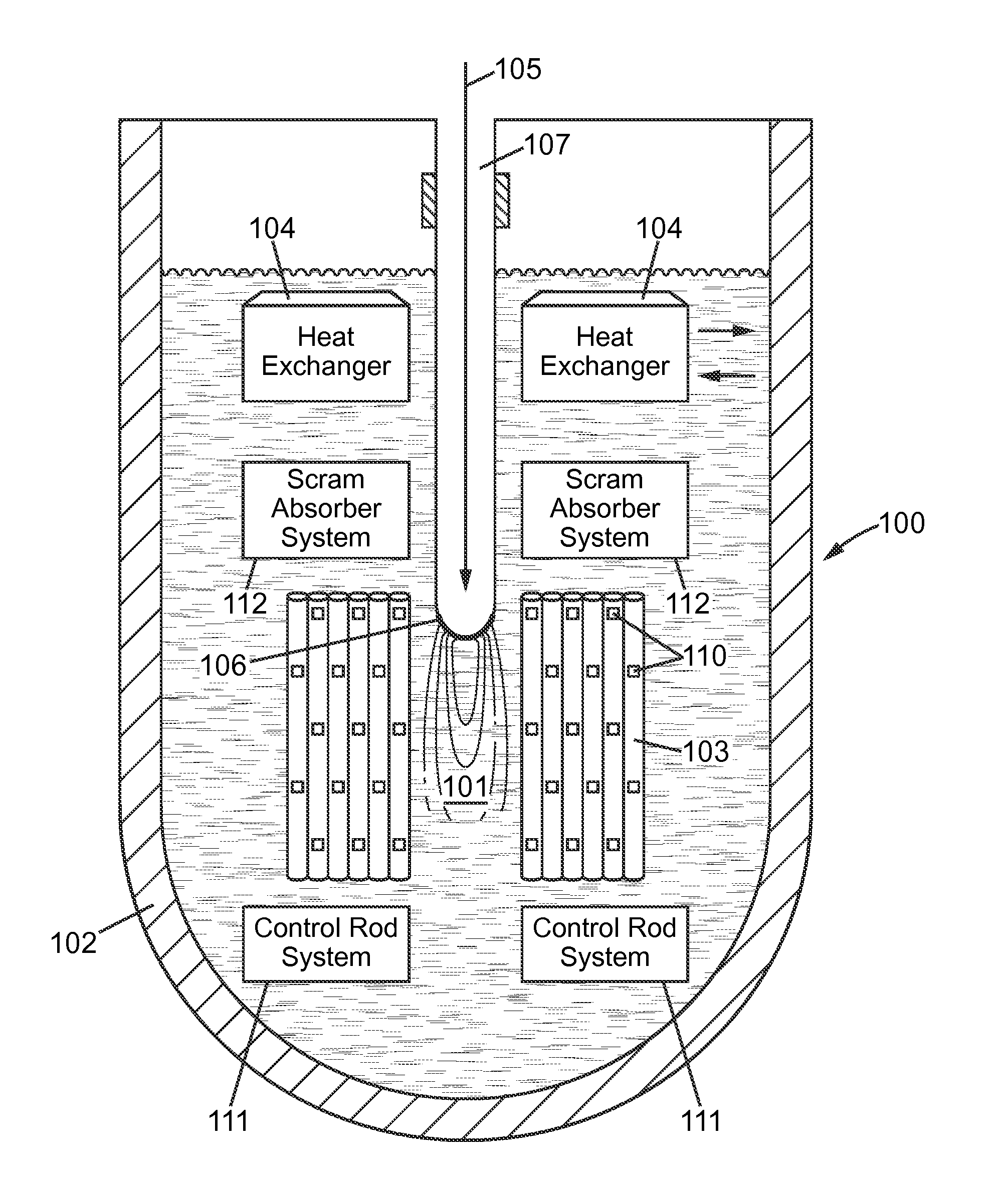
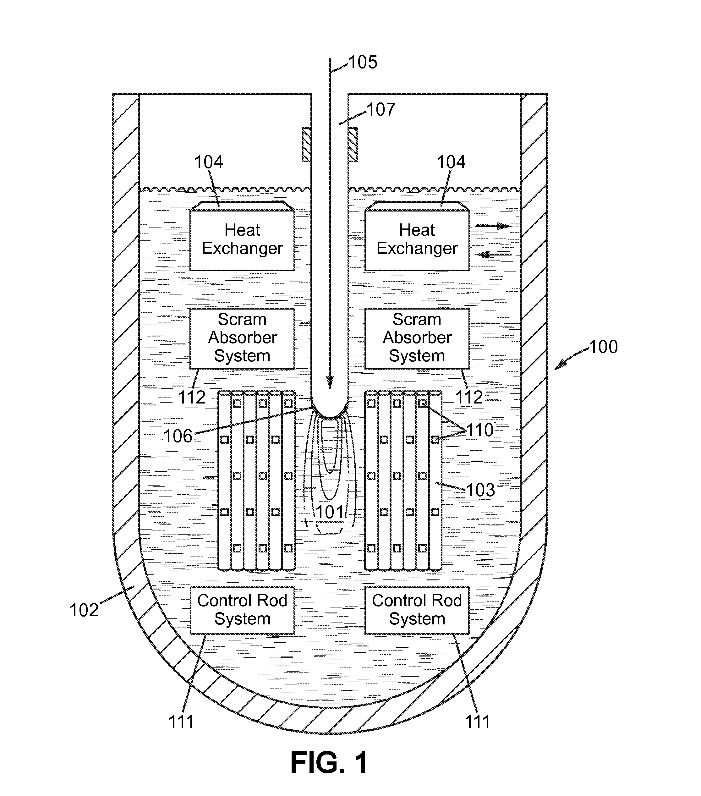
[0068]In an ADS as illustrated schematically in FIG. 1, spallation neutrons are generated in a target 101 located in a central region of a reactor core 100 by directing high energy particles, such as protons having a kinetic energy of the order of 1 GeV, onto heavy nuclei forming the target. Among different materials suitable for spallation targets, Lead is advantageously used because of its high neutron yield when hit by high energy protons. Also Lead in the liquid phase can be used as a coolant to recover thermal power from the core. Other elements including B...


PUM


Abstract

An accelerator-driven subcritical breeding reactor is operated with a neutron multiplication coefficient as large as possible in order to require a small input power from the accelerator, reducing its dimension and hence its cost and complexity. The beam-generated spallation neutron yield then becomes comparable to the fraction of delayed neutrons from the fissioned elements. This can be exploited to ensure an accurate on-line determination of the reactivity. Resulting changes can be adjusted with the help of neutron absorbing control rods and / or variations of the proton current. In addition, the temperature variations during operation can be continuously monitored and adjusted in order to avoid that the subcritical systems approaches too closely the (delayed) criticality condition and that the neutron multiplication coefficient remains within acceptable limits.

Description

BACKGROUND OF THE INVENTION[0001]The present invention relates to accelerator-driven systems (ADS).[0002]In the recent years, considerable interest has grown worldwide for accelerator-driven subcritical reactors for instance for Trans Uranic (TRU) burners and for a Thorium based breeder, the Energy Amplifier (EA) as disclosed in WO 95 / 12203.[0003]In a subcritical system, the neutron multiplication is less than one and the additional neutrons which are produced by an external proton accelerator can be used in particular to ensure the operation of the breeding reaction chain. Subcriticality appears particularly advantageous in applications where there is a contribution of the effective delayed neutrons much smaller than in an ordinary pressurized water reactor (PWR), a small or adverse Doppler temperature coefficient and possibly also a positive void coefficient depending on the conditions of the coolant. The subcritical operation is in particular helpful in the case of a fast breeder...

Claims


Application Information

Patent Timeline
Patent Type & Authority Applications(United States)
IPC IPC(8): G21D3/10G21C1/30G21C7/34
CPCG21C1/03G21C1/30G21C7/34Y02E30/39G21D3/10Y02E30/37G21C17/104Y02E30/00Y02E30/30G21C1/303
Inventor RUBBIA, CARLO
Owner JACOBS U K
Why Eureka
Try Eureka