Differential phase contrast x-ray imaging system and components

a contrast x-ray imaging and different phase technology, applied in the field of x-ray systems, can solve the problems of difficult fabrication of absorption gratings, inefficiency of crystal methods, and inability to enter the practical application field of crystal methods

Active Publication Date: 2013-01-31
THE JOHN HOPKINS UNIV SCHOOL OF MEDICINE
View PDF4 Cites 52 Cited by
  • Summary
  • Abstract
  • Description
  • Claims
  • Application Information

AI Technical Summary

Problems solved by technology

Although there are efforts to develop table-top synchrotrons [13], or to use narrow Kα lines from conventional tubes [14], the crystal method has not yet entered the domain of practical applications.
This is however quite inefficient.
The absorption gratings are difficult to fabricate; they are typically made by filling with gold the gaps in regular transmission gratings.
This method is however less useful at energies above a few tens of keV.
The reason is that it is difficult to fabricate micron-period absorption gratings with the thickness required to block higher energy X-rays.

Method used


Image

  • Differential phase contrast x-ray imaging system and components
  • Differential phase contrast x-ray imaging system and components
  • Differential phase contrast x-ray imaging system and components

Examples


further embodiments and examples

[0145]The following examples analyze the angular sensitivity needed for refraction enhanced imaging with the Talbot method and proposes ways to optimize the Talbot setup for improved refraction based imaging with conventional X-ray sources. Even though we use examples from medical and high energy density (HED) plasma imaging, the conclusions apply also to other fields, such as material sciences, NDT, or security.

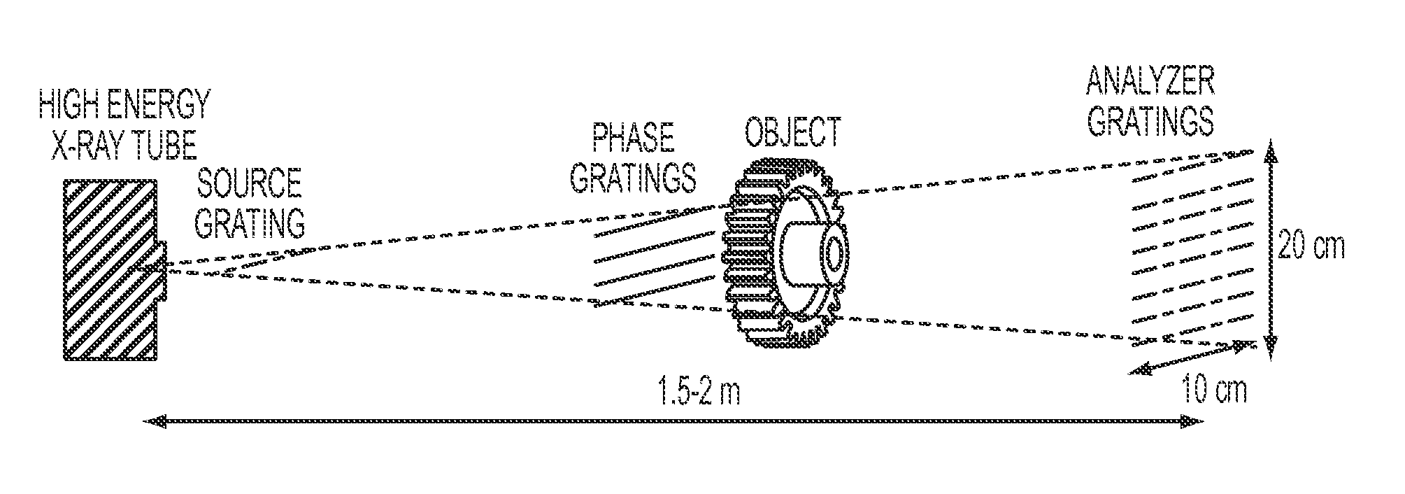
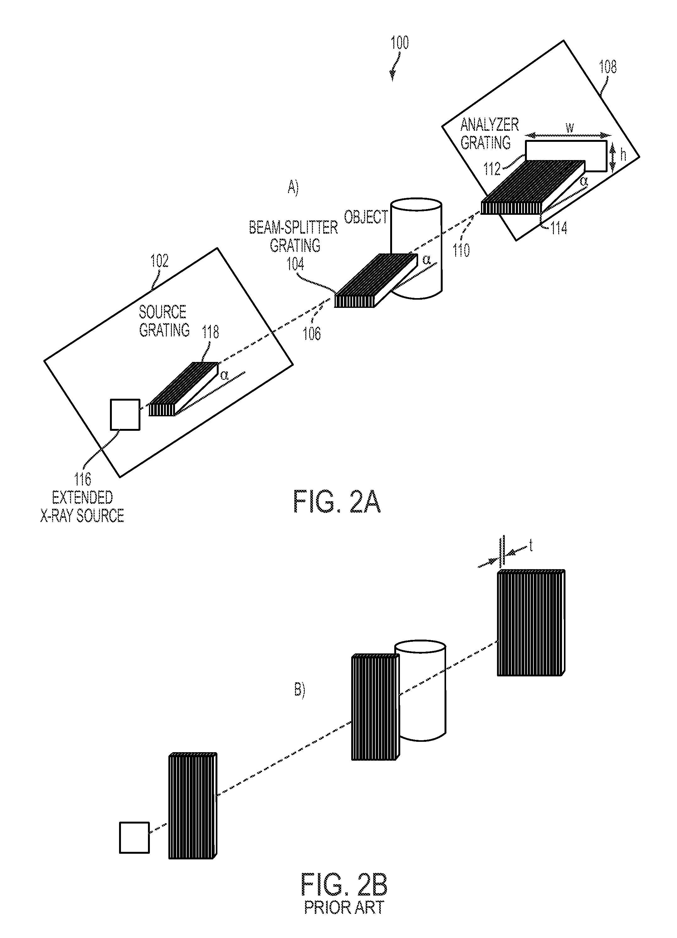
[0146]The Talbot interferometer is based on the Talbot effect, which consists of the production of micro-fringe patterns by a ‘beam-splitter’ grating illuminated by X-rays, at the so called Talbot distances dT=m g12 / 8λ, where λ is the wavelength, g1 is the grating period, and m=1, 3, 5 . . . is the order of the pattern. The basic interferometer consists of the beam-splitter (typically a π-shift phase grating) followed by an ‘analyzer’ absorption grating of period g2 equal to that of the Talbot fringe pattern and placed at the magnified Talbot distance D˜dT / (1−dT / L) from the ...


PUM

PropertyMeasurementUnit
shallow angleaaaaaaaaaa

Abstract

A differential phase contrast X-ray imaging system includes an X-ray illumination system, a beam splitter arranged in an optical path of the X-ray illumination system, and a detection system arranged in an optical path to detect X-rays after passing through the beam splitter.

Description

CROSS-REFERENCE OF RELATED APPLICATION[0001]This application claims priority to U.S. Provisional Application No. 61 / 513,175, filed Jul. 29, 2011, and 61 / 620,140, filed Apr. 4, 2012, the entire contents of which are hereby incorporated by reference.[0002]This invention was made with Government support of Grant No. DE-FG02-99ER54523, awarded by the Department of Energy; and Grant No. 1R21EB012777-01A1, awarded by the Department of Health and Human Services, The National Institutes of Health (NIH). The U.S. Government has certain rights in this invention.BACKGROUND[0003]1. Field of Invention[0004]The field of the currently claimed embodiments of this invention relates to X-ray systems, and more particularly to differential phase contrast X-ray imaging systems and X-ray illumination systems.[0005]2. Discussion of Related Art[0006]X-ray differential phase-contrast (DPC) imaging relies on the refraction of the X-rays passing through an object. Since for hard X-rays the refraction angles a...

Claims


Application Information

Patent Timeline
Patent Type & Authority Applications(United States)
IPC IPC(8): G01N23/04G21K3/00
CPCG01N23/04A61B6/482A61B6/583A61B6/484G01N23/20075A61B6/40A61B6/4042A61B6/4241A61B6/483A61B6/505A61B6/5235G21K1/067H05G2/001A61B6/4035A61B6/4291G21K2207/005G01N23/041G01N23/087G01N2223/206
Inventor STUTMAN, DANIELFINKENTHAL, MICHAEL
Owner THE JOHN HOPKINS UNIV SCHOOL OF MEDICINE
Why Eureka
Try Eureka