Optical add/drop multiplexer

a multiplexer and optical technology, applied in the field of optical fiber communication, can solve the problems of slow response, more difficult and challenging design than cwdm system, and difficult to extend, and achieve the effects of easy extension, quick response and low manufacturing cos

Inactive Publication Date: 2013-01-31
GP PHOTONICS INC
View PDF3 Cites 9 Cited by
  • Summary
  • Abstract
  • Description
  • Claims
  • Application Information

AI Technical Summary

Benefits of technology

[0008]In view of the above-described problems, it is one objective of the invention to provide an optical add / drop multiplexer having quick response, easy extension, and low manufacturing cost.
[0033]1. The optical add / drop multiplexer has the functions of adding and dropping from one or more ports or to one or more ports by means of acousto-optic tunable filter (AOTF), optical polarization power combiner (OPPC) and optical polarization power splitter (OPPS), and has the characteristics of quick response with sub-millisecond level wavelength switching time and short execution time.
[0035]3. The coupling of the optical add / drop multiplexer between the acousto-optic tunable filter (AOTF) and the wavelength blocker (WB) is implemented by fusing fiber pigtails of every apparatus connected in series, The use of fiber connection by fiber fusion has the advantage of the modularized manufacturing, and the high volume production at low cost can be realized.
[0036]4. The optical add / drop multiplexer can determine the wavelength of drop and add signals accurately by scanning the radio frequency source driving the AOTF, hence, the ROADM can be used in the dense wavelength division multiplexing (DWDM) and in the coarse wavelength division multiplexing (CWDM) systems by selecting a matched wavelength blocker.
[0037]5. The invention has the characteristics of compact design, quick response, short execution time, easy extension and low cost, and can be used in the dense wavelength division multiplexing (DWDM) and the coarse wavelength division multiplexing (CWDM) systems.

Problems solved by technology

DWDM is applied to high-level systems in communication hierarchy, however, it is more difficult and challenging to design than CWDM system.
There are some problems in existing optical add / drop multiplexers, such as slow response, difficult to extend and high manufacturing cost, etc.

Method used


Image

  • Optical add/drop multiplexer
  • Optical add/drop multiplexer
  • Optical add/drop multiplexer

Examples


Embodiment Construction

[0063]For further illustrating the invention, experiments detailing an optical add / drop multiplexer are described below. It should be noted that the following examples are intended to describe and not to limit the invention.

[0064]The preferred embodiment of the extensible and reconfigurable optical add / drop multiplexer is described in details below in conjunction with reference drawings, wherein identical reference numbers correspond to the identical components. Exemplary reference of an optical wavelength or a channel should be understood as an optical signal having a central wavelength and a particular bandwidth.

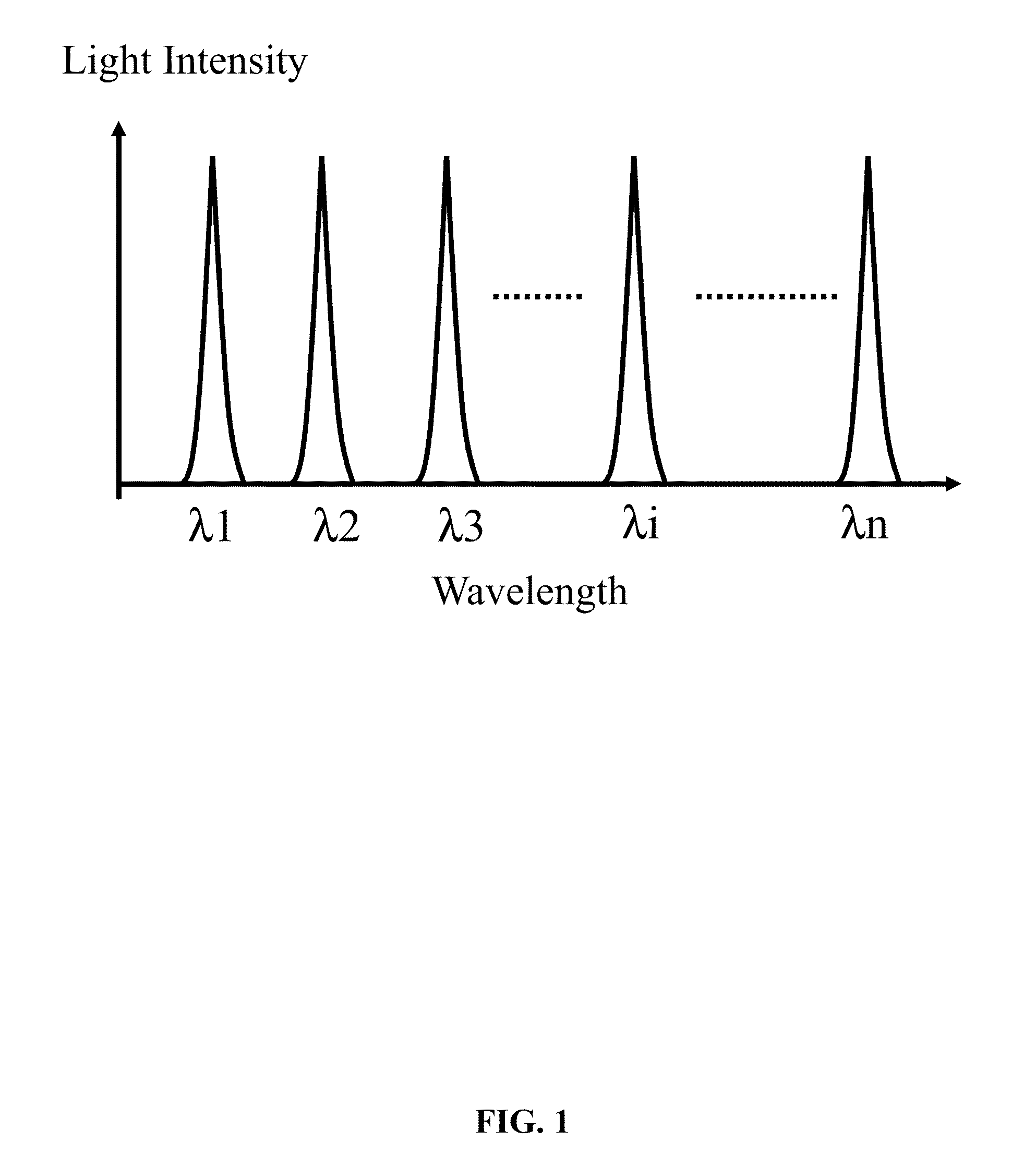
[0065]FIG. 1 shows a typical multi-wavelength optical signal with the equal channel spacing. The channel spacing is measured from the center of one channel to the center of adjacent channels. The multi-wavelength signal may be a multi-channel coarse wavelength division multiplexing (CWDM) signal, and the wavelength spacing between adjacent channels is approximately 20 nano...


PUM


Abstract

An optical add / drop multiplexer including one or more optical drop multiplexers connected in free space or fused by optical fiber pigtails, a wavelength blocker with an input port connected to an output port of the optical drop multiplexer through the fusion of the fiber pigtails, one or more optical add multiplexers connected in free space or fused by fiber pigtails, a digital signal processor, an analog-to-digital signal converter, a digital-to-analog converter, and a plurality of electronic control and feedback loops for tuning and scanning an optical wavelength.

Description

CROSS-REFERENCE TO RELATED APPLICATIONS[0001]This application is a continuation-in-part of International Patent Application No. PCT / CN2010 / 072624 with an international filing date of May 11, 2010, designating the United States, now pending, and further claims priority benefits to Chinese Patent Application No. 201010137637.7 filed Apr. 1, 2010. The contents of all the aforementioned applications, including any intervening amendments thereto, are incorporated herein by reference. Inquiries from the public to applicants or assignees concerning this document or the related applications should be directed to: Matthias Scholl P.C., Attn.: Dr. Matthias Scholl Esq., 14781 Memorial Drive, Suite 1319, Houston, Tex 77079.BACKGROUND OF THE INVENTION[0002]1. Field of the Invention[0003]The invention belongs to the field of optical fiber communication, and more particularly to an optical add / drop multiplexer.[0004]2. Description of the Related Art[0005]Wavelength division multiplexing (WDM) is o...

Claims


Application Information

Patent Timeline
Patent Type & Authority Applications(United States)
IPC IPC(8): H04J14/02
CPCG02B6/29383H04J14/0219H04J14/021G02B6/29395
Inventor GAO, PEILIANG
Owner GP PHOTONICS INC
Why Eureka
Try Eureka