Method of making a multimode optical fiber

a multi-mode optical fiber and manufacturing method technology, applied in the field of manufacturing optical fibers, can solve the problems of limiting bandwidth, affecting the bandwidth of optical fiber, and affecting the core of the moat interface,

Active Publication Date: 2013-01-31
CORNING INC
View PDF2 Cites 31 Cited by
  • Summary
  • Abstract
  • Description
  • Claims
  • Application Information

AI Technical Summary

Benefits of technology

[0006]In one aspect of the invention, a method of manufacturing a multimode optical fiber is disclosed comprising determining a refractive index profile n(r) of an optical fiber core preform at a predetermined wavelength λ; selecting a core delta Δfit, core radius afit and core shape parameter αfit that minimize the difference between n(r) and f(r)=n(0)[1−2Δfit(r/afit)αfit]1/2; selecting a draw tension T that obtains a predetermined optical fiber core shape parameter αfcr from αfit; calculating a refractive index ncl at λ of a cladding material obtained at a draw tension T; calculating a relative refractive index profile of a multimode optical fiber comprising optical fiber core shape parameter αfcr relative to ncl; calculating a target

Problems solved by technology

Any error at the core—moat interface may have a negative impact on the bandwidth of the optical fiber.
However, even with an optimum offset, perturb

Method used


Image

  • Method of making a multimode optical fiber
  • Method of making a multimode optical fiber
  • Method of making a multimode optical fiber

Examples


Embodiment Construction

[0039]Reference will now be made in detail to embodiments of the invention, examples of which are illustrated in the accompanying drawings. Whenever possible, the same reference numeral will be used throughout the drawings to refer to the same or like parts.

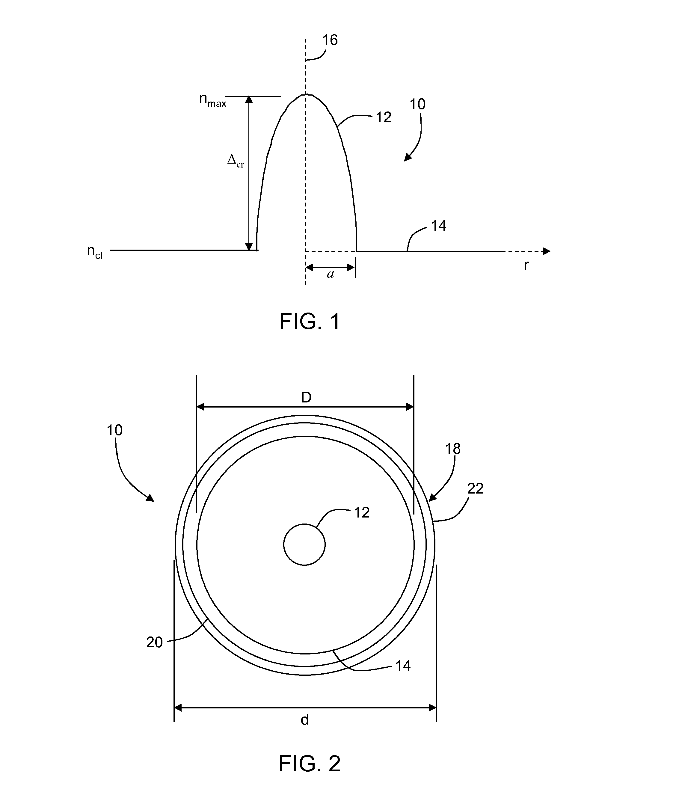
[0040]The “relative refractive index difference”Δ is defined as Δ=100×(ni2−nREF2) / 2ni2, where ni is the maximum refractive index in region i, unless otherwise specified herein. The relative refractive index difference is measured at 850 nm unless otherwise specified. The relative refractive index difference is typically referred to simply as “delta”. Unless otherwise specified, nREF is the average refractive index of the outermost annular region of the cladding, which can be calculated, for example, by taking “N” index measurements (ncl1, ncl2, . . . ncN) in the outermost annular region of the cladding (which in some embodiments may be undoped silica), and calculating the average refractive index by:

i=N

ncl=(1 / N)Σnci

i=1  (1)

[004...


PUM

PropertyMeasurementUnit
Lengthaaaaaaaaaa
Fractionaaaaaaaaaa
Fractionaaaaaaaaaa

Abstract

A method of making a multimode optical fiber is disclosed. In one embodiment the method includes calculating a core radius that maximizes the bandwidth of the multimode optical fiber wherein the effect of draw tension is accounted for. The embodiments herein illustrate how core radius can be tuned so the time delay of the outermost guided mode group is reduced. The resultant core radius may be targeted for a value off-nominal from what would be expected for a particular commercial optical fiber type.

Description

CROSS-REFERENCE TO RELATED APPLICATIONS[0001]This application claims the benefit of priority under 35 U.S.C. §119 of U.S. Provisional Application Ser. No. 61 / 425,477 filed on Dec. 21, 2010, the contents of which is hereby incorporated by reference.BACKGROUND[0002]1. Field of the Invention[0003]The present invention relates generally to the manufacture of optical fibers, and in particular a method of optimizing the bandwidth of multimode optical fibers.[0004]2. Technical Background[0005]To improve multimode optical fiber performance, bend insensitive multimode optical fibers have been developed. The fibers have improved the reliability of optical fiber communication systems, even when the highest order guided modes are excited. They are especially attractive for use in data center applications, where tight bends are a frequent necessity. While these designs may involve a depressed relative refractive index region, or “moat”, adjacent to the core, the optical fiber shape parameter alp...

Claims


Application Information

Patent Timeline
IPC IPC(8): G02B6/02
CPCG02B6/0288C03B37/01413C03B37/0253C03B2201/12C03B2205/40C03B2201/31C03B2201/32C03B2203/23C03B2203/26C03B2201/28Y02P40/57
Inventor BICKHAM, SCOTT ROBERTSONKOGAN, OLEKSANDRLI, MING-JUNMISHRA, SNIGDHARAJ KUMARTANDON, PUSHKAR
Owner CORNING INC
Why Eureka
Try Eureka