Coding device, error-correction code configuration method, and program thereof

a technology of error correction and configuration method, applied in the field of code conversion, error correction/detection using arithmetic codes, etc., can solve the problems of deterioration of error rate characteristics, more storage regions, and not necessarily high error correction capability of all blocks according to the weight distribution calculated in step sb>902/b>, so as to reduce the storage region and reduce the time for switching

Active Publication Date: 2013-01-31
NEC CORP
View PDF4 Cites 10 Cited by
  • Summary
  • Abstract
  • Description
  • Claims
  • Application Information

AI Technical Summary

Benefits of technology

[0033]As described above, the present invention is designed as the structure in which: the degrees of the cyclic permutation matrix are λ(j−i) when the components of the i-th row and the j-th column of the block inspection matrix are not a zero matrix; the degrees of the cyclic permutation matrix are λ(j−i) also when the components of the i+1-th row and the j+1-th column of the block inspection matrix are not a zero matrix; and the degrees of the cyclic permutation matrix are λ(j−i) also when the components of the i+2-th row and the j+2-th column of the block inspection matrix, the components of the i+3-th row and the j+3-th column of the block inspection matrix, and thereafter are not a zero matrix. Thus, the storage region required for holding the inspection matrix generated by the present invention can be reduced to be about (q+1−r)×r bits. Further, the use of the mask pattern makes it possible to generate many kinds of inspection matrices of different coding rates from the same data and further to switch the inspection matrices instantly.
[0034]Thereby, it is possible to provide the coding device, error-correction code configuration method, and program thereof, which exhibit the excellent characteristics such as being able to reduce the storage region required for using a plurality of low-density-parity-check codes (LDPC) and to reduce the time for the switching at the time of using those properly.

Problems solved by technology

Further, as described above, all the blocks according to the weight distributions calculated in step S902 do not necessarily have a high error correction capability.
However, when there is a regularity between the values of each of the degrees u(i, j), the error rate characteristic is deteriorated.
In particular, in a communication system which uses a plurality of different LDPC codes of different coding rates, frame lengths, error rate characteristic, and the like according to the factors such as the state of the communication path, there are such issues that still more storage regions are required for holding the inspection matrix and the time required for switching the coding device becomes greater.
However, there is no special consideration taken for shortening the time required for the switching, so that it does not overcome that point of issue.

Method used


Image

  • Coding device, error-correction code configuration method, and program thereof
  • Coding device, error-correction code configuration method, and program thereof
  • Coding device, error-correction code configuration method, and program thereof

Examples


first exemplary embodiment

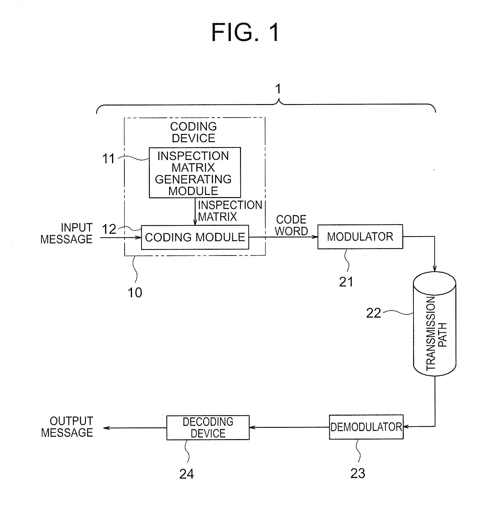
[0047]Hereinafter, the structure of a first exemplary embodiment of the present invention will be described by referring to the accompanying drawing FIG. 1.

[0048]The basic contents of the exemplary embodiment will be described first, and the more specific contents thereof will be described thereafter.

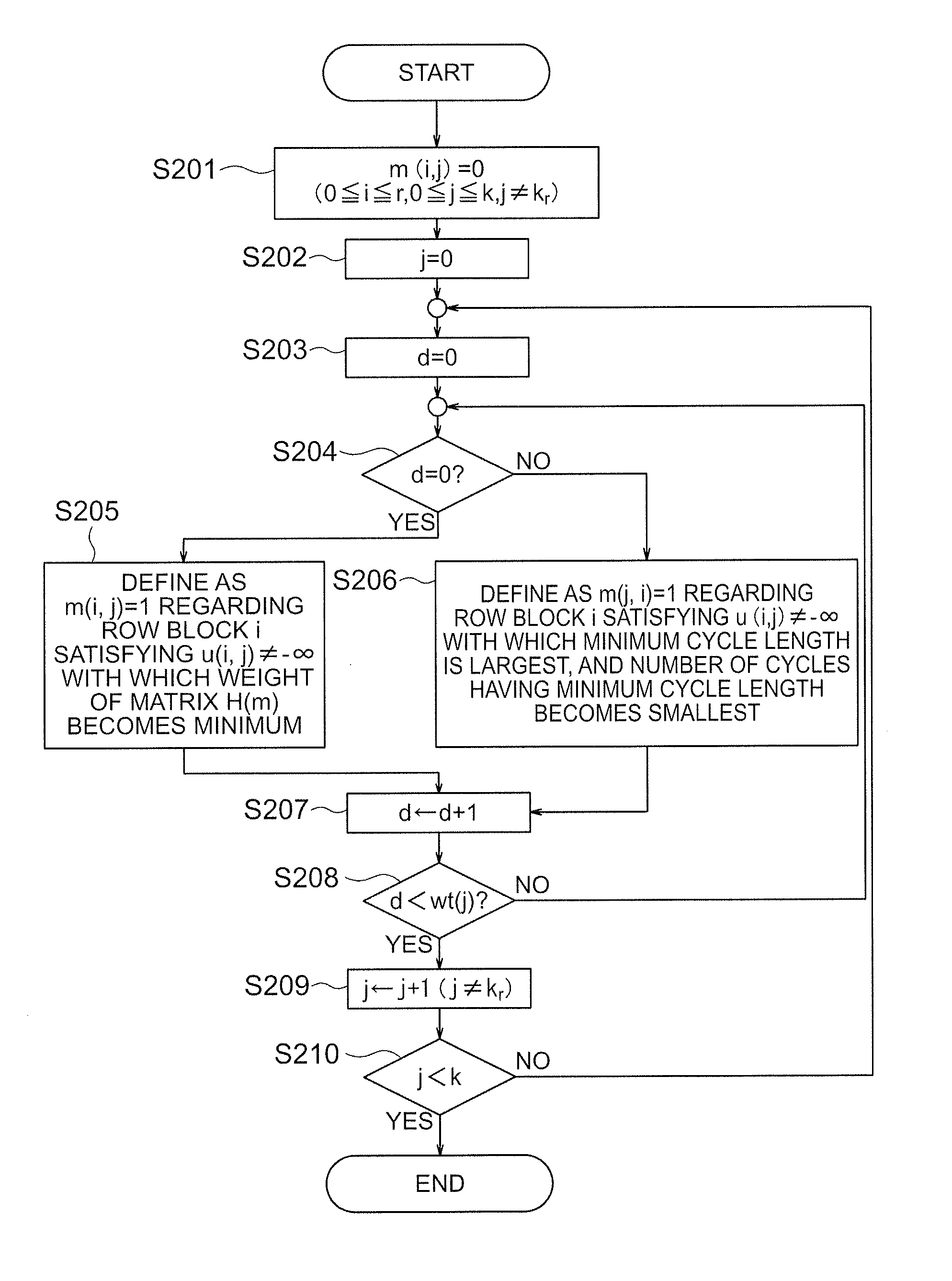
[0049]As shown in FIG. 1, a coding device 10 according to the exemplary embodiment includes: an inspection matrix generating module 11 which generates a block inspection matrix of the quasi-cyclic low-density-parity-check (LDPC) code that is a cyclic permutation matrix where number of rows and number of columns are both q−1 or a zero matrix as components (q is an integer of 4 or larger and a power of 2), number of row blocks is r and number of column blocks is q+1 (r is an integer between 4 and q, inclusive), and i-th row block and j-th column block components (i is an integer between 0 and r−1, j is an integer between 0 and q, left-end column of the matrix is defined as 0th column, and...

second exemplary embodiment

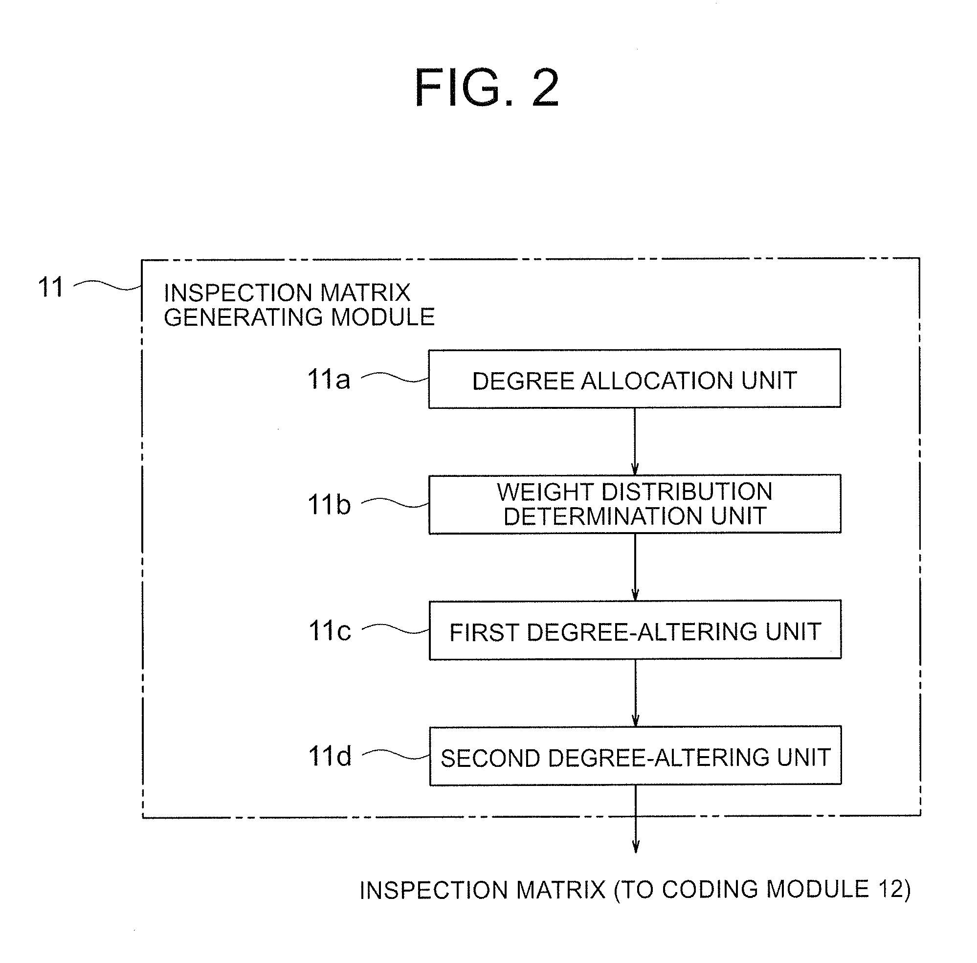
[0116]In addition to the structure of the coding device 10 according to the first exemplary embodiment, a coding device 110 according to a second exemplary embodiment of the present invention is so structured that: the weight distribution determination unit 11b of the inspection matrix generating module defines all the components of q+1−n pieces of column blocks among q+1−r pieces of column blocks excluding the r−1 piece of the column block on the right end and the k_r-th column block of the q+1 pieces of the column blocks of the block inspection matrix; and the inspection matrix generating module includes a column block cancel unit 111e which cancels q+1−n pieces of column blocks whose entire components are zero matrix.

[0117]With this structure, it is possible to acquire the same effect as that of the first exemplary embodiment. Further, the column block number of the inspection matrix to be generated can be set to an arbitrary number of r+1 and q+1, inclusive, so that it is possib...


PUM


Abstract

A coding device includes: an inspection matrix generating module that generates a block inspection matrix; and a coding module that generates and outputs a code word from an input message by the inspection matrix. The inspection matrix generating module includes: a degree-allocation unit that prescribes function values of the block inspection matrix by the coefficients of a self-reciprocal polynomial expression; a weight distribution determination unit that prescribes the number of components that are non-zero matrices among the components of each block of the block inspection matrix using a mask pattern; a first degree-altering unit that considers the sum of the components of the k_r-th row block of the block inspection matrix as a cyclic permutation matrix; and a second degree-altering unit that prescribes the row-block number of components that are non-zero matrices among the components of each row block excluding said k_r-th row block of the clock inspection matrix.

Description

TECHNICAL FIELD[0001]The present invention relates to a coding device, an error-correction code configuration device, and a program thereof. More specifically, the present invention relates to a coding device and the like which structure many kinds of quasi-cyclic low-density-parity-check codes with a small storage region.BACKGROUND ART[0002]For transmissions and storages of digital signals such as satellite communications, mobile communications, optical disks, and the like, reduction in required electric power, reduction in the size of antenna, improvements in the transmission speed (or storage capacitance), and the like are required at all times. In order to satisfy such demands, error correction coding techniques having a large coding gain are being employed. Among those, the low-density-parity-check (referred to as LDPC code hereinafter) is known as the error correction code having a large coding gain, and it is being employed more and more into the above-described various kinds...

Claims


Application Information

Patent Timeline
Patent Type & Authority Applications(United States)
IPC IPC(8): H03M13/07
CPCH03M13/033H03M13/1188H03M13/116
Inventor KAMIYA, NORIFUMI
Owner NEC CORP
Why Eureka
Try Eureka