
Microelectromechanical gyroscope with self-calibration function and method of calibrating a microelectromechanical gyroscope

a microelectromechanical gyroscope and self-calibration technology, which is applied in the direction of calibration apparatus, measurement devices, instruments, etc., can solve the problems of systematic errors that alter the results of measurements, unbalance of capacitance, and complex structure of mems gyroscopes

Active Publication Date: 2013-02-07
STMICROELECTRONICS SRL
View PDF16 Cites 35 Cited by
  • Summary
  • Abstract
  • Description
  • Claims
  • Application Information

AI Technical Summary

Benefits of technology

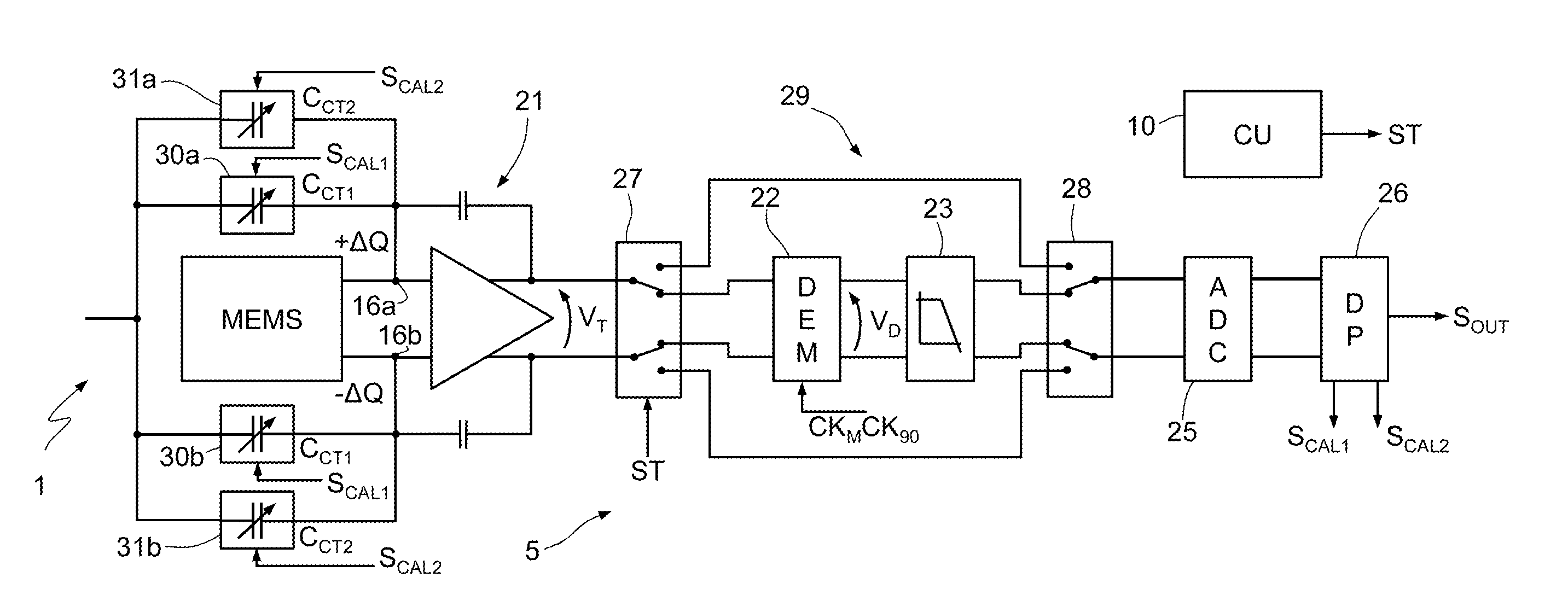
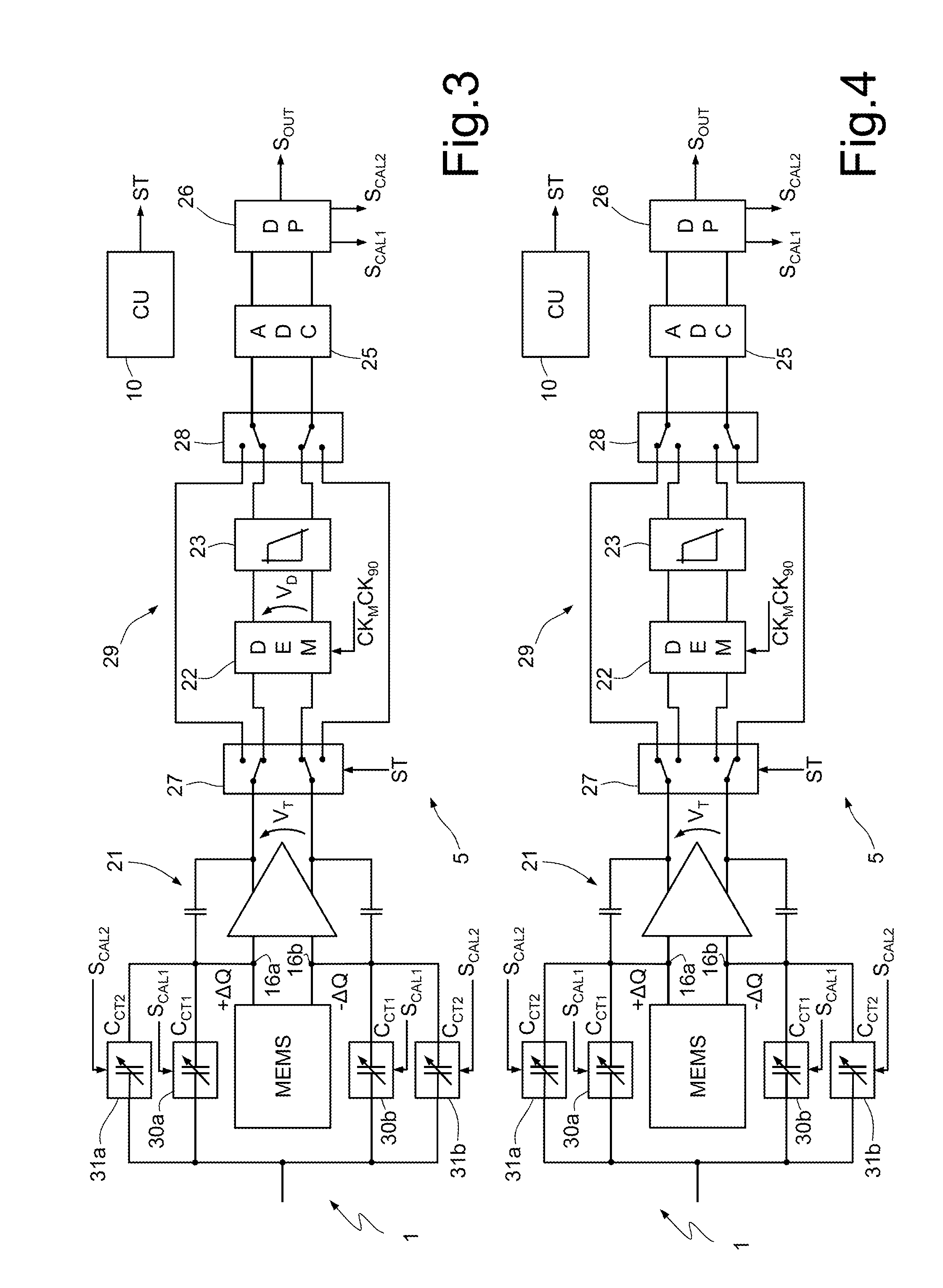
The present invention provides a microelectromechanical gyroscope and a method for calibrating it that can overcome the limitations of previous devices. The new device includes a sensing mass that can move in response to rotations of the supporting structure, and a reading interface that can detect changes in capacitance between the sensing mass and the supporting structure. Calibration components can detect and modify systematic errors in the transduction signals, resulting in a more accurate measure of rotation.

Problems solved by technology

As already mentioned, the structure of MEMS gyroscopes is rather complex and, among other things, the exact configuration of the masses and of the electrodes necessary for driving and sensing affects the capacitive coupling.
In practice, inevitable imperfections due to process spread result in systematic errors that alter the results of the measurements.
For instance, a defect in the elastic suspension elements that constrain the masses to the stator can cause a displacement with respect to the theoretical resting position and hence an unbalancing of the capacitances.
The systematic unbalancing due to the process spread (offset) carries, however, a considerable weight and as a rule has a much greater effect than the unbalancing caused by the measured quantity (in particular, an angular velocity).
Even though the offset is translated in frequency by demodulation and subsequently filtered, the dynamics of the components that intervene in the processing prior to filtering is severely limited.
Furthermore, even when the dynamics available for the useful signal is sufficient, the demodulation and filtering cannot cause total suppression of the contribution of offset, which presents in a form similar to the noise on the output.
Also this aspect may seriously limit the use of microelectromechanical gyroscopes, especially for applications where an extremely low level of noise is required.
This solution is not, however, satisfactory, because the offsets linked to the structure, especially due to capacitive unbalancing, are not stable and depend to a large extent upon the conditions, in particular the temperature.
Even just the thermal stresses during the steps of soldering of the devices can cause important drifts and annuls the effect of calibration.
In the same way, variations of temperature in use with respect to the calibration conditions may modify the offset and alter the measurements, introducing systematic errors.

Method used


Image

  • Microelectromechanical gyroscope with self-calibration function and method of calibrating a microelectromechanical gyroscope
  • Microelectromechanical gyroscope with self-calibration function and method of calibrating a microelectromechanical gyroscope
  • Microelectromechanical gyroscope with self-calibration function and method of calibrating a microelectromechanical gyroscope

Examples


Embodiment Construction

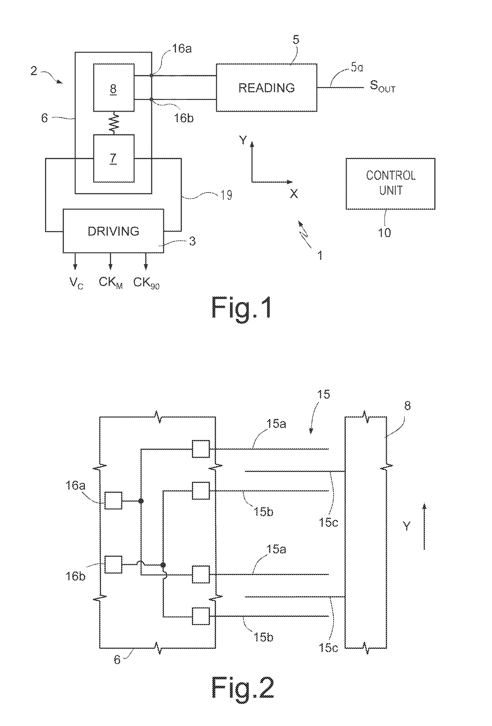
[0022]FIG. 1 shows as a whole a microelectromechanical gyroscope 1, which comprises a microstructure 2, of a semiconductor material, a driving device 3, a reading generator 4, a reading device 5, and a control unit 10.

[0023]The microstructure 2 is made of a semiconductor material and comprises a supporting structure 6, a driving mass 7, and at least one sensing mass 8. For reasons of simplicity, in the embodiment illustrated herein reference will be made to the case of a uniaxial gyroscope, in which only one sensing mass 8 is present. What is described hereinafter applies, however, also to the case of multiaxial gyroscopes, which comprise two or more sensing masses or systems of sensing masses, for detection of rotations according to respective independent axes.

[0024]The driving mass 7 is elastically constrained to the supporting structure 6 so as to be able to oscillate about a resting position according to a translational or rotational degree of freedom. The sensing mass 8 is mech...


PUM


Abstract

A microelectromechanical gyroscope having a supporting structure; a mass capacitively coupled to the supporting structure and movable with a first degree of freedom and a second degree of freedom, in response to rotations of the supporting structure about an axis; driving components, for keeping the mass in oscillation according to the first degree of freedom; a read interface for detecting transduction signals indicating the capacitive coupling between the mass and the supporting structure; and capacitive compensation modules for modifying the capacitive coupling between the mass and the supporting structure. Calibration components detect systematic errors from the transduction signals and modify the capacitive compensation modules as a function of the transduction signals so as to attenuate the systematic errors.

Description

BACKGROUND[0001]1. Technical Field[0002]The present disclosure relates to a microelectromechanical gyroscope with a self-calibration function and to a method for calibrating a microelectromechanical gyroscope.[0003]2. Description of the Related Art[0004]As is known, the use of microelectromechanical systems (MEMS) has become increasingly widespread in various sectors of technology and has yielded encouraging results especially in the production of inertial sensors, microintegrated gyroscopes, and electromechanical oscillators for a wide range of applications.[0005]MEMS of this type are usually based upon microelectromechanical structures comprising at least one mass connected to a fixed body (stator) by springs and movable with respect to the stator according to pre-set degrees of freedom. The movable mass and the stator are capacitively coupled through a plurality of respective comb-fingered electrodes facing one another so as to form capacitors. The movement of the movable mass wi...

Claims


Application Information

Patent Timeline
IPC IPC(8): G01C25/00
CPCG01C19/5776
Inventor DONADEL, ANDREAUNGARETTI, TOMMASOCAMINADA, CARLOPRANDI, LUCIANO
Owner STMICROELECTRONICS SRL
Learn More