
Gas meter for ultrasound measurements in a breathing apparatus

a technology of ultrasound measurement and gas meter, which is applied in the direction of liquid/fluent solid measurement, sensors, medical devices, etc., can solve the problems of erroneous time of flight measurement, severe deterioration of ultrasound measurement accuracy, etc., and achieve the effect of improving the reliability of ultrasound measuremen

Active Publication Date: 2013-02-07
MAQUET CRITICAL CARE
View PDF6 Cites 6 Cited by
  • Summary
  • Abstract
  • Description
  • Claims
  • Application Information

AI Technical Summary

Benefits of technology

The present invention aims to improve the reliability of ultrasound measurements on a gas in a breathing apparatus. One way to achieve this is by designing a gas conduit with a slightly bent, cylindrical conduit of uniform thickness that is upwardly convex relative to the horizontal plane. This design helps to increase the velocity of the gas within the measurement chamber, which in turn increases accuracy in the ultrasound measurements. Additionally, the gas conduit is shaped such that the at least one surface that is inclined relative to the horizontal plane to give the self-draining effect simultaneously serves as a constriction of the flow channel, which further enhances the accuracy of the ultrasound measurements. The gas conduit can be produced by providing the gas conduit with substantially planar inner walls that constitute top, bottom, and side walls of the gas conduit, and the top wall may form a substantially horizontal, planar ceiling of the gas conduit. The design of the gas conduit also helps to prevent condensation water from penetrating the transducer cavity and filling the air gap normally existing between the transducer and the transducer housing, which further minimizes the risk of transducer short-circuiting. The gas meter may also include a heat generator, such as a resistive heating film, arranged to locally heat the area around the or each transducer to further prevent the risk of condensation water penetrating the transducer cavity and filling the air gap.

Problems solved by technology

One problem which may occur if condensation water accumulates in the measurement chamber is that it may reflect the acoustic pulses such that the travel distance and hence the time of flight for the pulses is changed.
This problem mainly arises in single-transducer arrangements in which a single ultrasonic transducer mounted on one side of the gas conduit is used both to transmit acoustic pulses through the gas and to receive the pulses after being reflected by the inner wall on the opposite side of the gas conduit, or a reflector element arranged on the opposite side of the gas conduit.
In such a single-transducer arrangement, condensation water on the inner wall or reflector element may severely deteriorate the accuracy in the determination of gas flow or composition.
Another problem may occur if condensation water is gathered around the ultrasonic transducer itself.
If condensation water penetrates the air gap normally existing between the transducer and the transducer housing, the acoustic pulses may propagate through the material of the transducer housing and further on through the gas conduit, giving rise to various undesired effects.
This problem mainly arises in double-transducer arrangements in which two ultrasonic transducers, one acting as a transmitter and the other as a receiver, are arranged on opposite sides of the gas conduit.
Such a “short-circuiting” of the ultrasound transducers will, of course, result in erroneous time of flight measurements.

Method used


Image

  • Gas meter for ultrasound measurements in a breathing apparatus
  • Gas meter for ultrasound measurements in a breathing apparatus
  • Gas meter for ultrasound measurements in a breathing apparatus

Examples


first embodiment

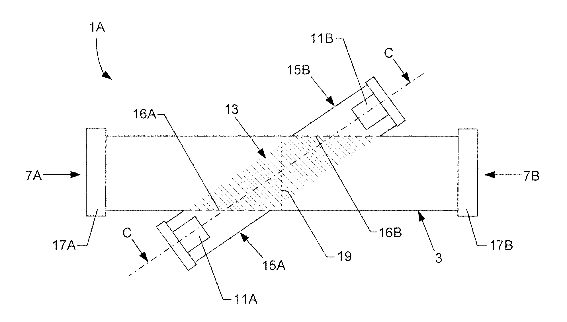
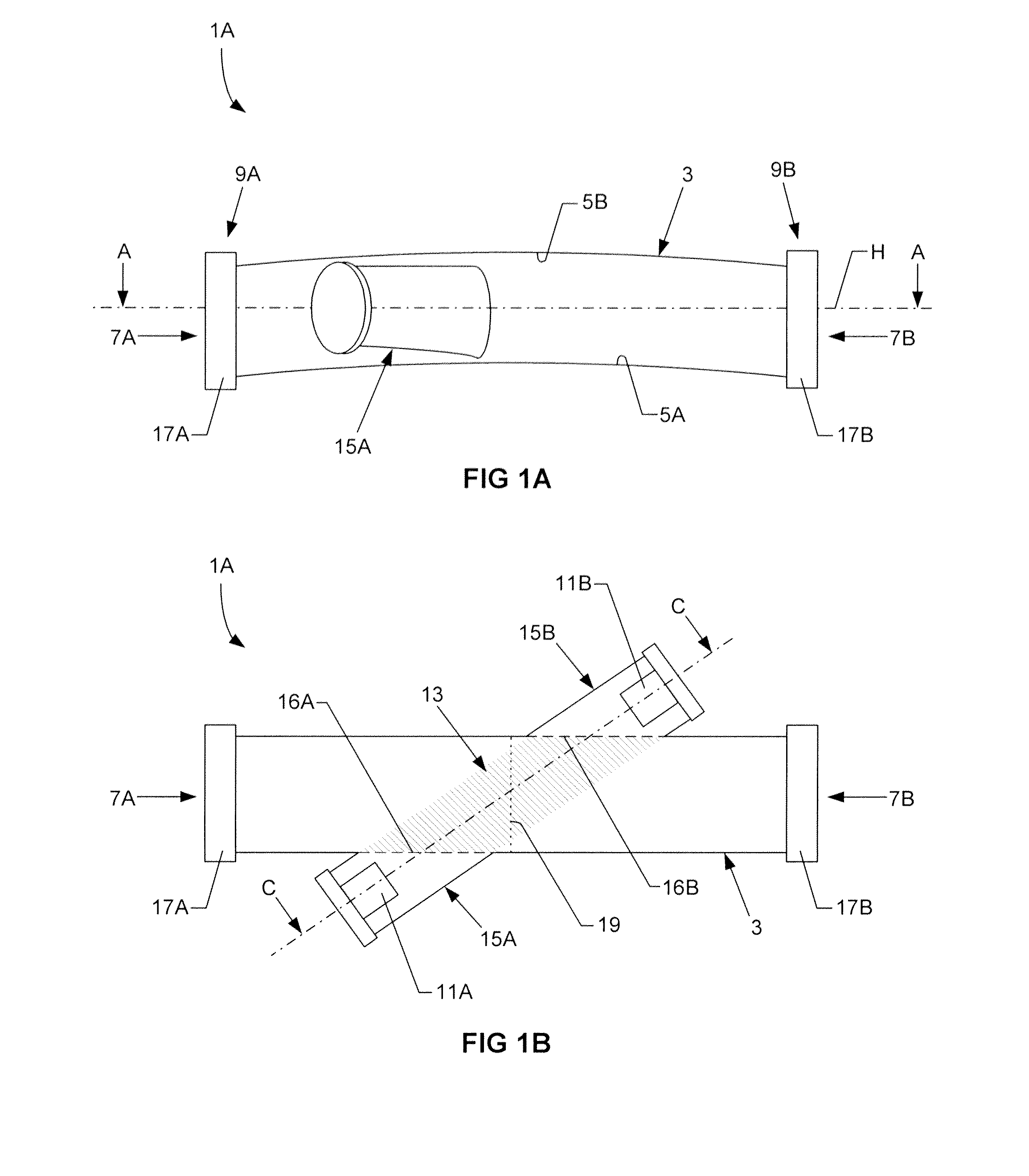
[0032]FIG. 1A illustrates a side view of a gas meter 1A for ultrasound measurements in a breathing apparatus according to the invention. The gas meter 1A has a gas conduit 3 having an inner wall defining an inlet 7A in a first end 9A of the gas conduit and an outlet 7B in a second end 9B of the gas conduit. The inner wall has a lower inner wall surface 5A and an upper inner wall surface 5B. In this embodiment, the gas conduit 3 is preferably a cylindrical conduit of uniform thickness which is upwardly convex relative to the horizontal plane, illustrated by the dash-dotted line denoted H. Of course, the gas conduit 3 does not have to be a cylindrical conduit having a circular cross section. For example, the gas conduit 3 could be a quadrilateral tube having a rectangular cross section. It should be appreciated that any spatial term used herein, such as “upwardly”, refers to the gas meter when orientated as shown in FIGS. 1A and 2A of the drawings, which is the intended orientation of...

second embodiment

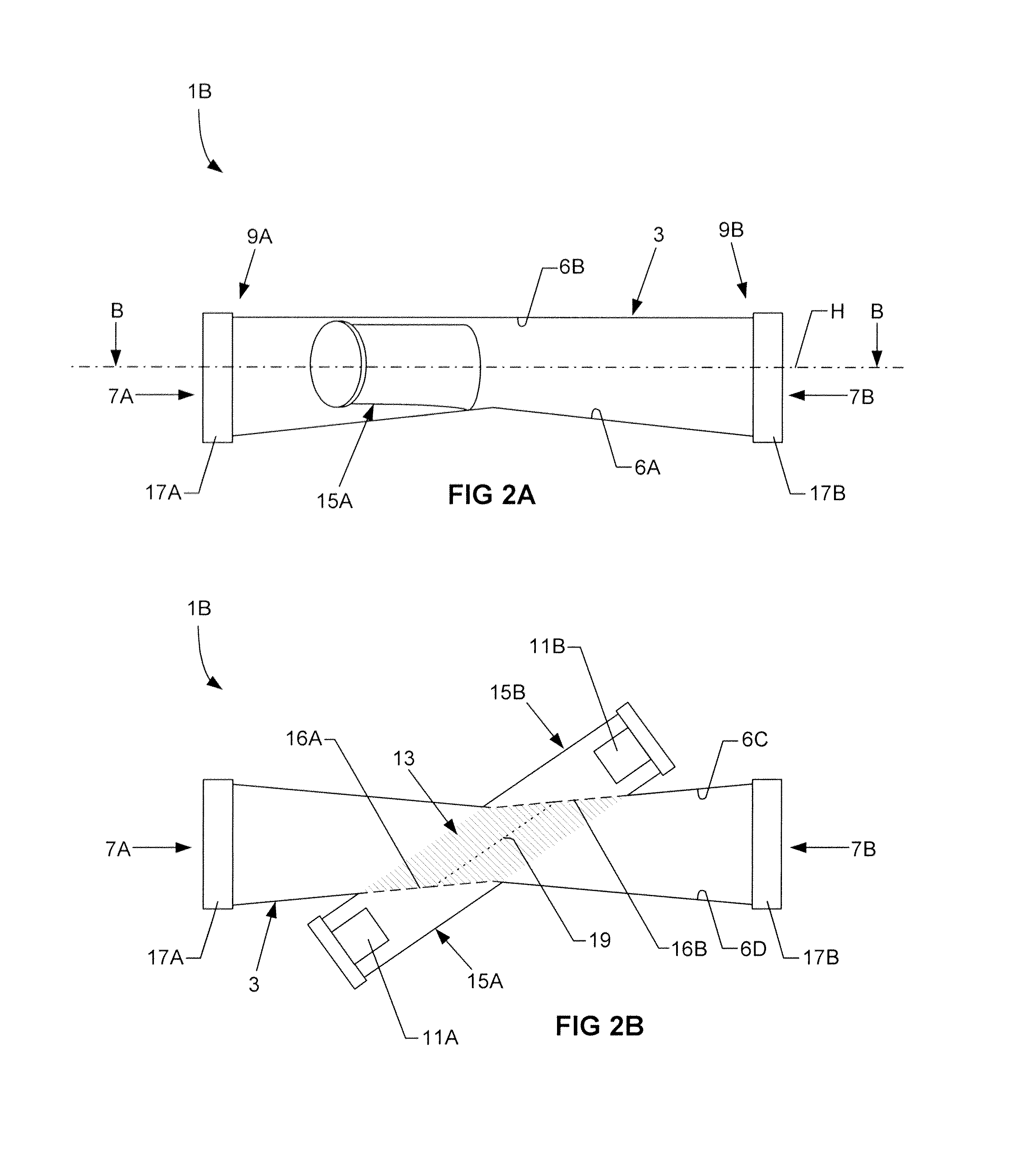
[0038]FIG. 2A illustrates a side view of a gas meter 1B for ultrasound measurements in a breathing apparatus according to the invention.

[0039]With reference to FIG. 2B, which illustrates a cross-sectional view of the gas meter 1B taken along the line B-B in FIG. 2A, the gas conduit 3 is shown as having four substantially planar inner wall portions 6A-6D, constituting bottom, top, and side walls, respectively, of the gas conduit 3. The lower inner wall surface 6A of the gas conduit 3 has a substantially constant, positive slope from the inlet 7A to the measurement chamber 13, and a substantially constant, negative slope from the measurement chamber 13 to the outlet 7B. Thus, the lower inner wall surface 6A of the gas conduit 3 has an inverted V-shape in the longitudinal direction of the gas conduit 3, with the base of the inverted ‘V’ being located within the measurement chamber 13. The dotted line 19 in FIG. 2B illustrates the highest point of the lower inner wall surface 6A of the ...


PUM


Abstract

A gas meter for ultrasound measurements in a breathing apparatus has a gas conduit having an inner wall defining an inlet in a first end of the gas conduit and an outlet in a second end of the gas conduit, and an ultrasound transducer arrangement configured to measure the speed of sound in a gas flowing through a part of said gas conduit forming a measurement chamber. The gas meter has a self-draining design to prevent condensation water and other liquids from negatively affecting the ultrasound measurements. To this end, at least a lower surface of the inner wall of the gas conduit is inclined downwardly relative to the horizontal plane in the longitudinal direction of the gas conduit, at both sides of the measurement chamber causing condensation water to be pulled away from the measurement chamber by gravity.

Description

BACKGROUND OF THE INVENTION[0001]1. Field of the Invention[0002]The present invention relates to a gas meter for ultrasound measurements in a breathing apparatus of the type having a gas conduit with an inner wall that defines an inlet at a first end of the gas conduit and outlet in a second end of the gas conduit, and having an ultrasound transducer arrangement that measures the speed of sound in a gas flowing through a part of the gas conduit that forms a measurement chamber.[0003]2. Description of the Prior Art[0004]Ultrasonic gas meters for measuring the flow or the composition of a gas are well known in the art and commonly used in breathing apparatuses, such as ventilators and anaesthesia machines. Such a gas meter typically operates by determining the time of flight for an acoustic (ultrasonic) pulse transmitted through the gas flowing through a gas conduit of the breathing apparatus. The time of flight may then be used to determine the flow of the gas if the gas composition ...

Claims


Application Information

Patent Timeline
IPC IPC(8): A61M16/00
CPCA61B5/087A61M2016/0033G01F1/662A61M2205/3375A61M2016/102
Inventor REUTERHOLT, JOHANDANIELSEN, LARS
Owner MAQUET CRITICAL CARE
Learn More