Check patentability & draft patents in minutes with Patsnap Eureka AI!

Integrated microfluidic check valve and device including such a check valve

Inactive Publication Date: 2013-02-07
TELEDYNE DALSA SEMICON
View PDF8 Cites 52 Cited by
  • Summary
  • Abstract
  • Description
  • Claims
  • Application Information

AI Technical Summary

Benefits of technology

The technical effect of this patent is that it ensures that there is always the same pressure in both chambers, even if there is too much pressure in one chamber. This allows a membrane to deflect into the other chamber, allowing for better control and performance of the device.

Problems solved by technology

Despite a number of designs for microfabricated check-valves in general, existing designs are only suitable for fabricating discrete components.
For LOC devices, which have moved strongly towards laminated structures that are built from discrete layers, existing check-valve designs are inappropriate.
Unfortunately, this approach has the significant drawback that additional control signals need to be routed off-chip, and then supplied by external infrastructure.
This affects the cost and reliability of LOC technologies when applied to an application (for example, a molecular biology protocol).
Also, the relatively large size of pneumatic connections limits the amount of functionality that can be integrated on a chip, increasing overall system costs.
Additionally, as a mechanical connection must be made at the time of use, pneumatic connections reduce reliability and increase the need for operator training.
The lack of suitable check-valves therefore triples the number of off-chip pneumatic connections required for each pump.
The costs, in terms of on-chip routing, chip-to-world interfaces, and off-chip macroscopic pneumatic valves, are therefore tripled due to the absence of effective check-valves.

Method used


Image

  • Integrated microfluidic check valve and device including such a check valve
  • Integrated microfluidic check valve and device including such a check valve
  • Integrated microfluidic check valve and device including such a check valve

Examples


Embodiment Construction

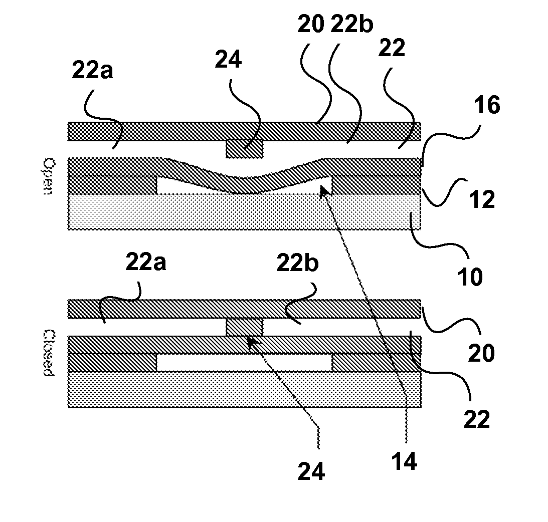
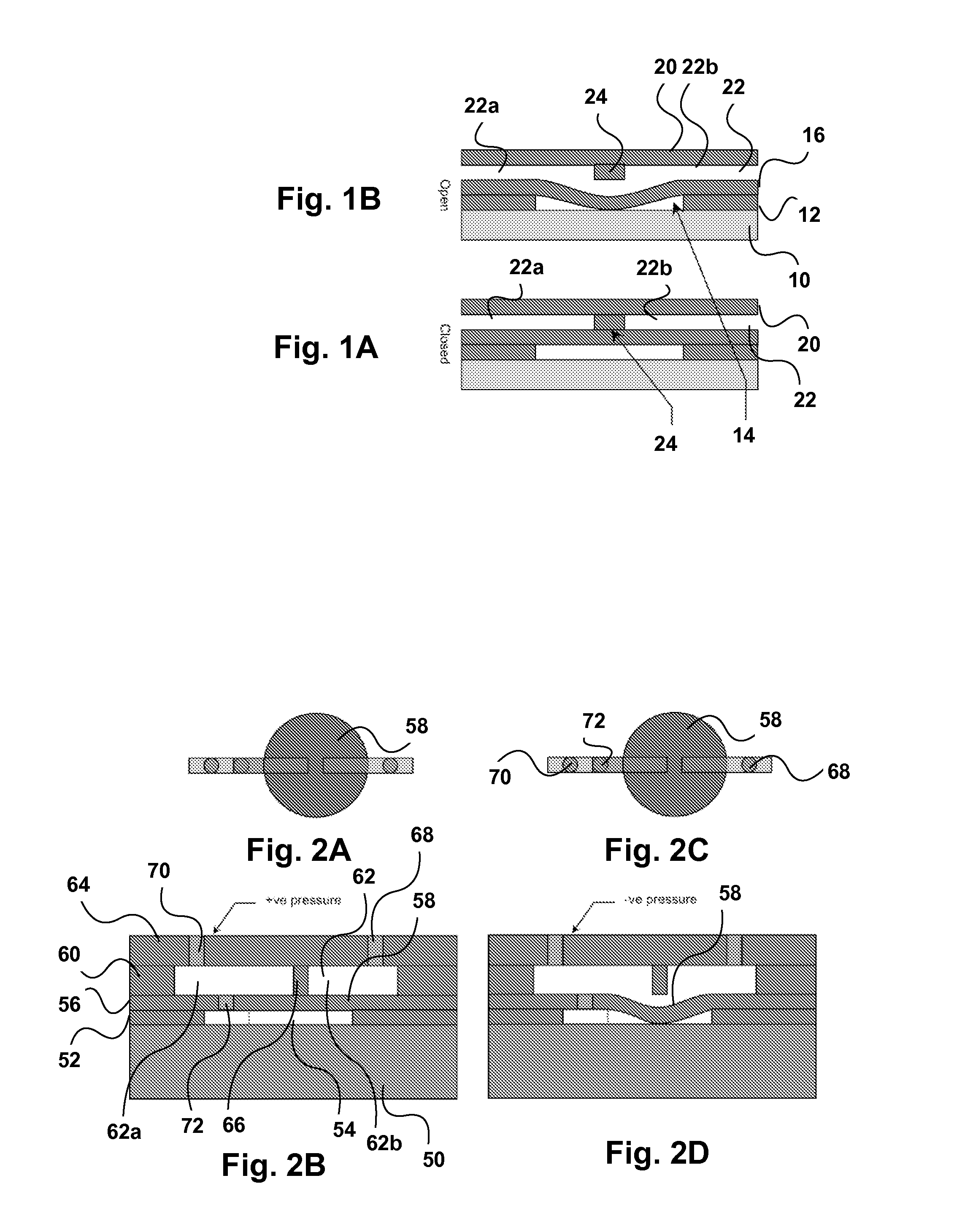
[0017]A prior art valve, known as a Mathies' valve, is shown in FIGS. 1A-1B, where FIG. 1A shows the valve in the open position and FIG. 1B shows the valve in the closed position. Such a valve is described in the paper by W. H. Grover et al. entitled “Monolithic Membrane Valves and Diaphragm Pumps for Practical Large-Scale Integration in Glass Microfluidic devices” Sensors and Actuators B, vol. 89, no. 3, pg. 315-323 (2003), the contents of which are herein incorporated by reference. The valve consists of a substrate 10, a pneumatic layer 12 defining a chamber 14, a membrane layer 16, a cap layer 20 defining a fluid passage 22, and a barrier 24 dividing the fluid passage 22 into parts 22a, 22b.

[0018]Etched into the fluid layer are channels (not shown) for water or some other liquid. An analyte for a chemical or medical application flows through these channels.

[0019]Etched into the pneumatic layer 12 are channels (not shown) for the pneumatic signals, which are either compressed air...


PUM

PropertyMeasurementUnit
Pressureaaaaaaaaaa
Flow rateaaaaaaaaaa

Abstract

An integrated microfluidic check valve has a first chamber having inlet and outlet ports and divided by a barrier the said inlet and outlet ports into first and second subchambers. A membrane forms a wall of the first chamber and co-operates with the barrier to selectively permit and prevent fluid flow between the inlet and outlet ports. A second chamber adjoining the first chamber and has a wall formed by the membrane. A microfluidic channel establishes fluid communication between the second chamber and the first subchamber. The membrane deflects to permit fluid flow around the barrier when the pressure in the first subchamber is lower than the pressure in the second subchamber. Two such valves can be combined into a peristaltic pump.

Description

FIELD OF THE INVENTION[0001]This invention relates to the field of microfluidic systems, and more particularly to a microfluidic a microfluidic check valve and a device including such a check valve.BACKGROUND OF THE INVENTION[0002]A common component in any fluidic system is the check-valve, which allows fluid to flow in one direction, while preventing flow in the opposite direction. Check-valves are therefore important components for controlling the direction of flow. Further, the opening pressure of some check-valves can be tailored to control the amount of positive pressure necessary to initiate flow, and these types of check-valves can also be used to passively regulate pressure. As such, check-valves are a fundamental component in the design of fluidic systems.[0003]In the design of microfluidic systems, it is extremely useful to have access to methods and designs to fabricate miniature check-valve. Despite a number of designs for microfabricated check-valves in general, existin...

Claims


Application Information

Patent Timeline
IPC IPC(8): F15C1/06B21K1/20F16K15/00
CPCF04B43/02F04B53/1062F16K99/0015Y10T29/49405F16K2099/008F16K2099/0094F16K99/0057Y10T137/7837Y10T137/2224
Inventor JOHNSTONE, ROBERTMARTEL, STEPHANE
Owner TELEDYNE DALSA SEMICON
Features
  • R&D
  • Intellectual Property
  • Life Sciences
  • Materials
  • Tech Scout
  • Unparalleled Data Quality
  • Higher Quality Content
  • 60% Fewer Hallucinations
Learn More