
Radiation image capturing apparatus

a technology of radioactive irradiation and capturing apparatus, which is applied in the direction of radioactive control devices, instruments, television systems, etc., can solve the problems of image data, the decline of the conversion efficiency of radiation into electric charges, and the difficulty in building an interface between the devices, so as to improve the image quality of the radiological image and detect the initiation of radioactive irradiation accurately

Inactive Publication Date: 2013-02-07
KONICA MINOLTA MEDICAL & GRAPHICS INC
View PDF22 Cites 48 Cited by
  • Summary
  • Abstract
  • Description
  • Claims
  • Application Information

AI Technical Summary

Benefits of technology

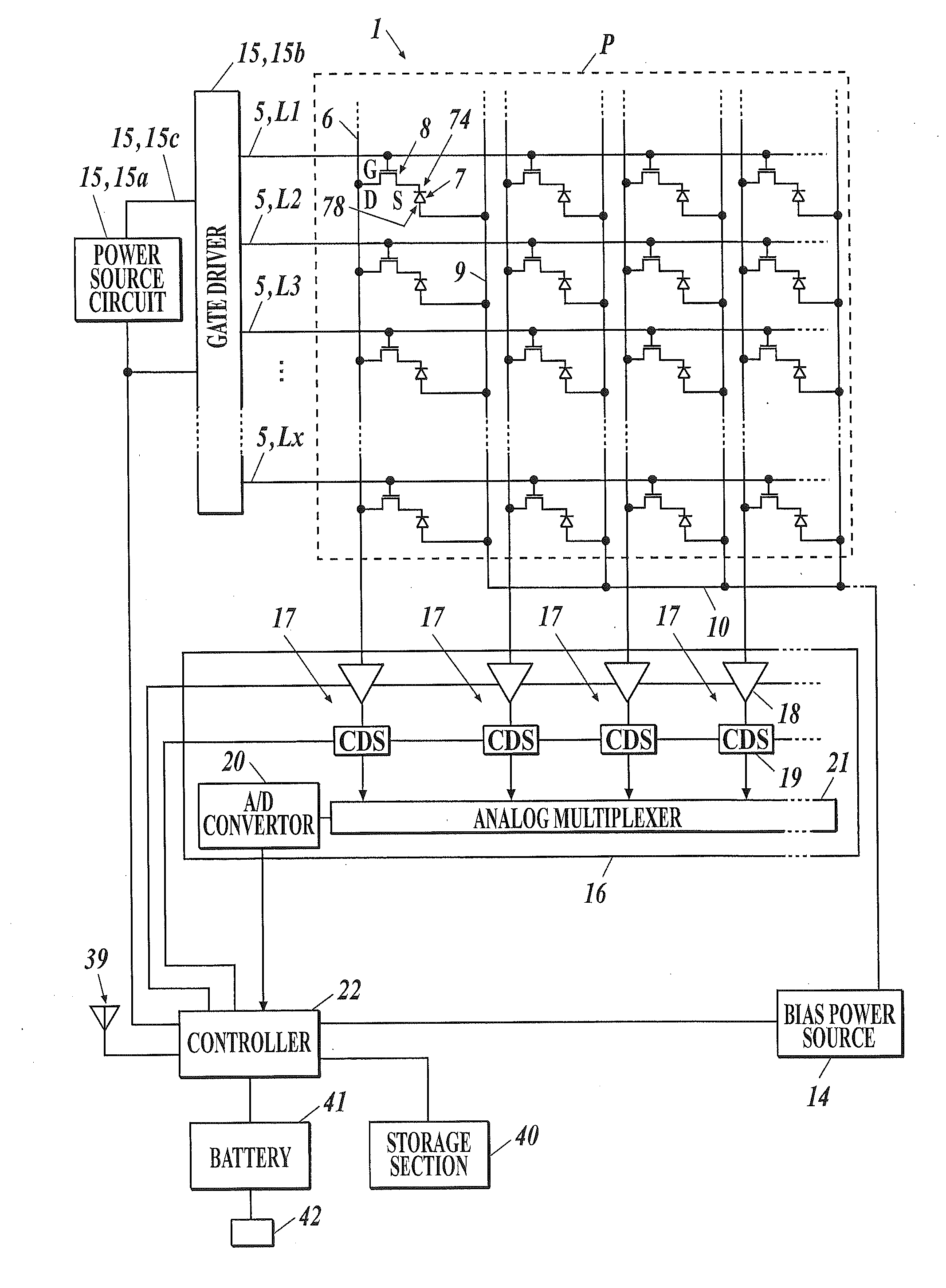
The present invention relates to a radiation image capturing apparatus that can detect the initiation of radioactive irradiation accurately without needing an interface with a radiation generator. This is achieved by using the properties of a switch unit that a leakage current flowing through it is increased due to radioactive irradiation. By detecting the initiation of radioactive irradiation accurately, the apparatus can improve image quality of a radiological image generated based on the image data without consuming additional power or generating noise.

Problems solved by technology

However, in the case of this configuration, it is required that an interface should be constructed in a precise manner between the radiation image capturing apparatus and the radiation generator, and the radiation image capturing apparatus side should be able to accumulate electric charges in each of the radiation detection elements at the stage of radioactive irradiation, but construction of an interface between the devices is not necessarily easy.
There has been a problem that, if the interface is not constructed precisely, radioactive irradiation begins while a reset process is executed on the side of the radiation image capturing apparatus for discharging excessive electric charges remaining in each of the radiation detection elements, and electric charges generated by the radioactive irradiation, in other words, electric charges which should be read out without fail as useful information regarding the subject is reflected in the amount thereof escapes from each of the radiation detection elements in the reset process, causing decline of conversion efficiency of radiation into electric charges, namely, image data.

Method used


Image

  • Radiation image capturing apparatus
  • Radiation image capturing apparatus
  • Radiation image capturing apparatus

Examples


first embodiment

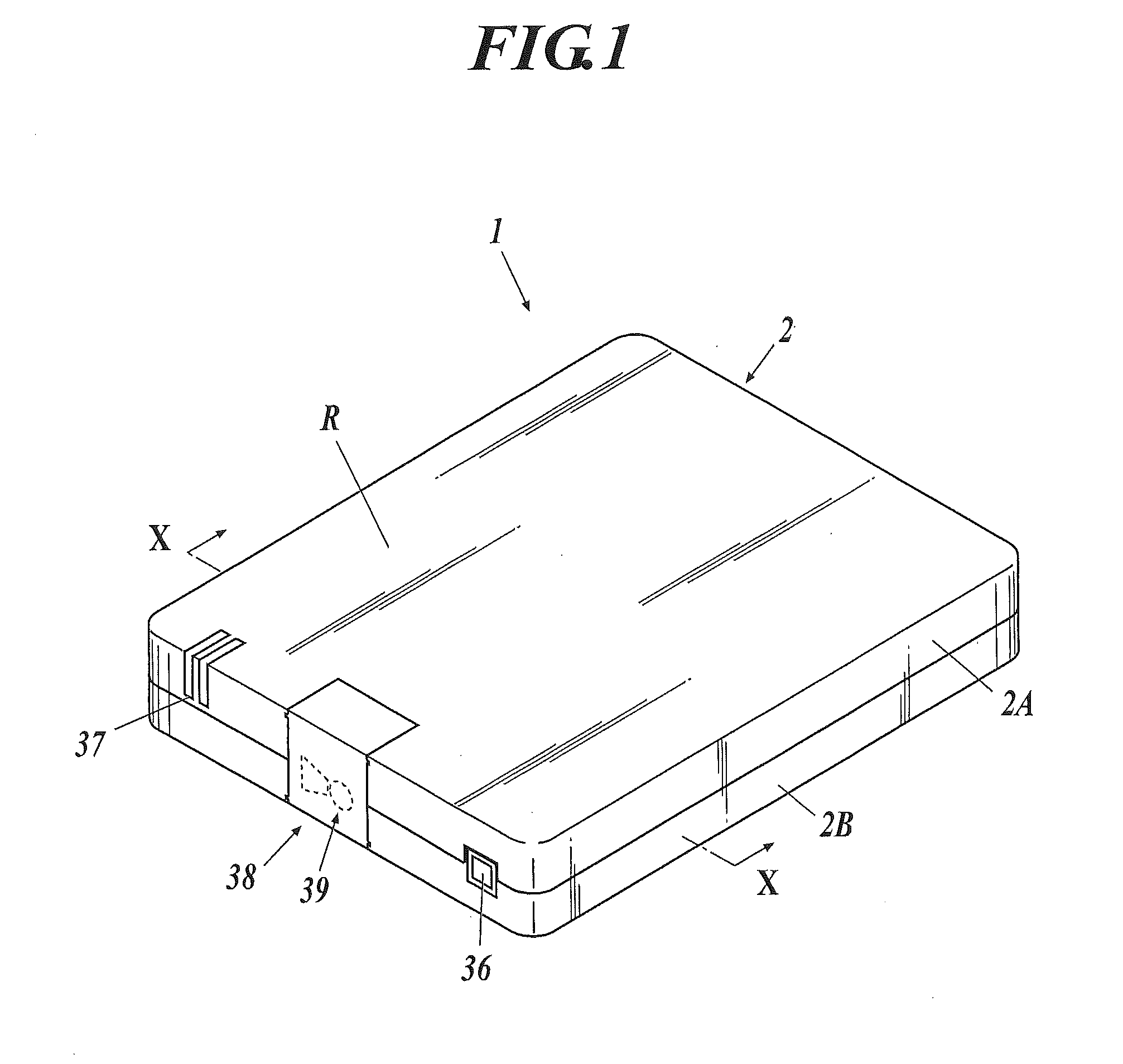
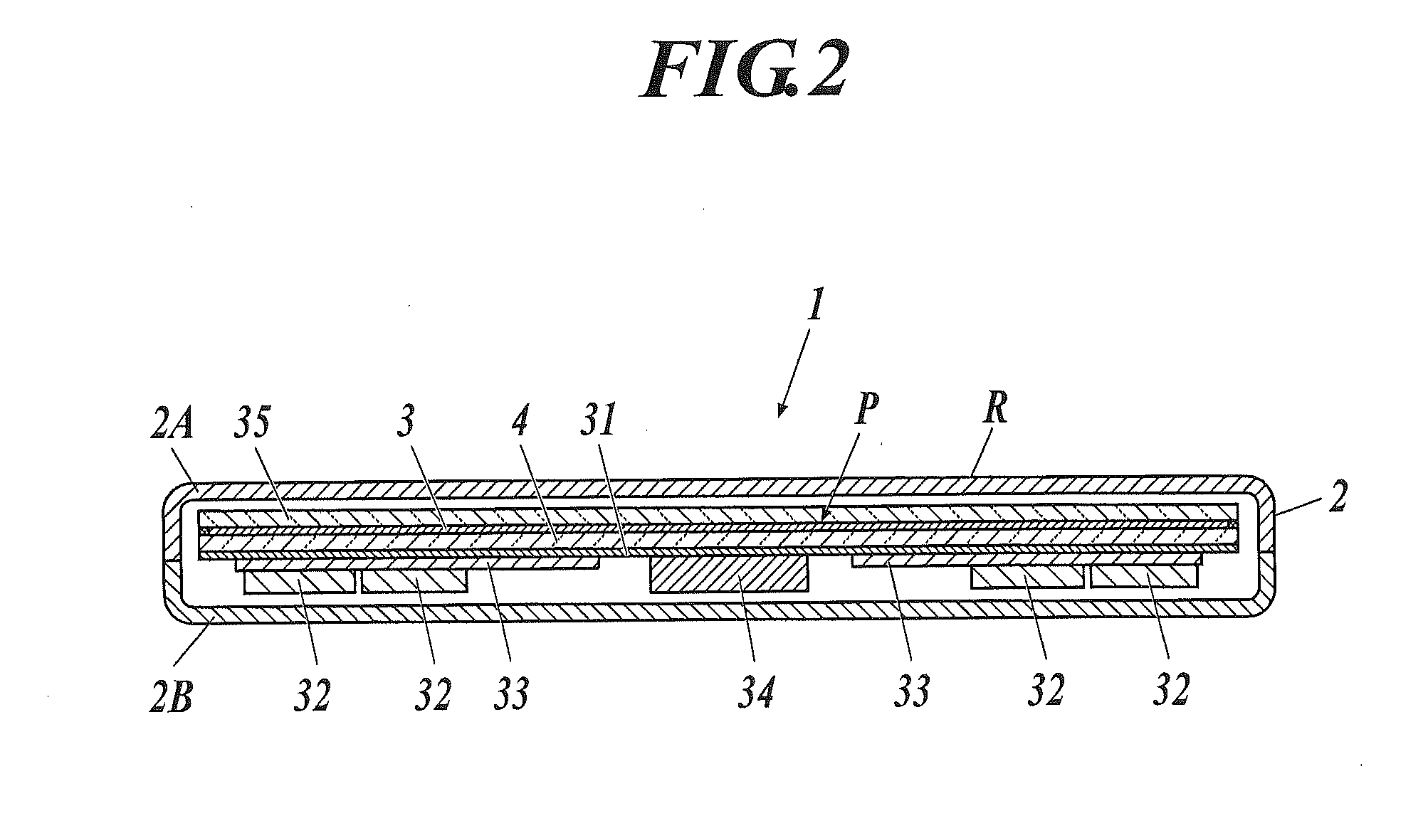
[0086]FIG. 1 is an external perspective view of a radiation image capturing apparatus according to this embodiment, and FIG. 2 is a cross-sectional view along the line X-X in FIG. 1. The radiation image capturing apparatus 1 according to this embodiment is constructed by storing a scintillator 3, a substrate 4 and so on in a case 2 as illustrated in FIGS. 1 and 2.

[0087]In the case 2, at least a radiation entrance face R is formed from a material such as a carbon plate and plastic through which radiation can pass. FIGS. 1 and 2 show a case where the case 2 has a so-called rectangular lunch-box shape, formed of a frame plate 2A and a back plate 2B, but the case 2 may also have a so-called monocoque shape in which the case 2 is formed integrally into a square tube shape. Further, as illustrated in FIG. 1, a power source switch 36, an indicator 37 constructed by LED or the like, a cover member 38 which can be opened and closed for changing a battery 41 (see FIG. 7 described later), and ...

second embodiment

[0332]In the aforementioned first embodiment, as stated above, respective processes were explained from the leaked data readout process before radiation image capturing operation (including the reset process of each of the radiation detection elements 7 and the image data readout process for each of the radiation detection elements 7, which are conducted during this process), the electric charge accumulation mode during radiation image capturing operation, and to the image data readout process after radiation image capturing operation. In the second embodiment, a process for obtaining an offset correction value O will be explained, which is executed after the image data readout process in a normal radiation image capturing apparatus.

[0333]The offset correction value O is also called a dark readout value and is equivalent to an offset of the image data d, which a dark electric charge and the like which is generated and accumulated in each of the radiation detection elements 7 due to ...

example 1

Construction Example 1

[0346]As explained in Assumption 3 above, although the offset correction value O does not increase in proportion to the TFT 8 off period, the offset correction value O becomes the same value if the TFT 8 off period is the same. Therefore, for example, such construction may be adapted so that the TFT 8 off period of each of the lines L of the scanning lines 5 becomes the same off period in both the image data readout process and the offset correction value readout process in the following way.

[0347]Namely, as shown in FIG. 41, after executing the leaked data readout process and the reset process for each of the radiation detection elements 7 before radiation image capturing operation, transition to the electric charge accumulation mode, and the image data readout process for each of the radiation detection elements 7 after radiation image capturing operation, the leaked data readout process and the reset process for each of the radiation detection elements 7, tr...


PUM


Abstract

A radiation image capturing apparatus includes: a detecting section, a scanning drive unit, switch units, reading circuits, and a controller. The controller controls at least the scanning drive unit and the reading circuits and causes the same to execute data readout process from the radiation detection elements. The controller causes the reading circuits to periodically perform a readout operation before radiation image capturing operation in a state where each of the switch units is in an off state by applying the off voltage to all of the scanning lines from the scanning drive unit, causes the reading circuits to repeatedly execute a leaked data readout process in which the electric charges leaked from the radiation detection elements through the switch units are converted into leaked data, and detects initiation of irradiation at a point when the read-out leaked data exceeds a threshold value.

Description

TECHNICAL FIELD[0001]The present invention relates to a radiation image capturing apparatus, particularly to a radiation image capturing apparatus capable of detecting initiation of radioactive irradiation etc. by itself.BACKGROUND ART[0002]There has been development of various types of radiation image capturing apparatuses including a so-called direct-type radiation image capturing apparatus that generates an electric charge through a detection element in response to an irradiation dose of radiation such as X-rays and converts the electric charge into an electric signal, and a so-called indirect-type radiation image capturing apparatus that uses a scintillator etc. to convert the applied radiation into electromagnetic waves such as visible light having other wavelengths, then generates an electric charge through a photoelectric conversion element such as a photodiode in response to the energy of the electromagnetic wave having been converted and applied, and converts the electric c...

Claims


Application Information

Patent Timeline
Patent Type & Authority Applications(United States)
IPC IPC(8): H01L27/146
CPCA61B6/42A61B6/4258A61B6/4405A61B6/54A61B6/542H01L27/14632H04N5/32H04N5/3575H04N5/361H04N5/367H04N5/378G01T1/247H01L27/14663A61B6/4233A61B6/4283H04N25/616H04N25/68H04N25/30H04N25/78H04N25/63H04N25/75
Inventor TAJIMA, HIDEAKI
Owner KONICA MINOLTA MEDICAL & GRAPHICS INC
Learn More