
X-ray compton scatter imaging on volumetric CT systems

Active Publication Date: 2013-02-07
GEORGIA TECH RES CORP
View PDF1 Cites 14 Cited by
  • Summary
  • Abstract
  • Description
  • Claims
  • Application Information

AI Technical Summary

Benefits of technology

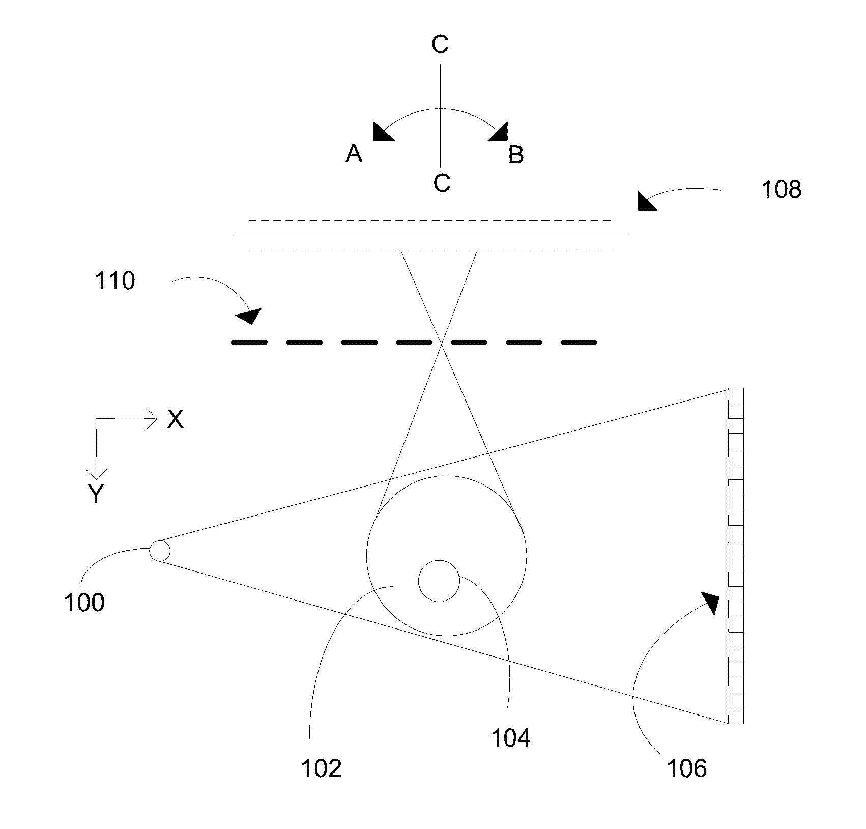
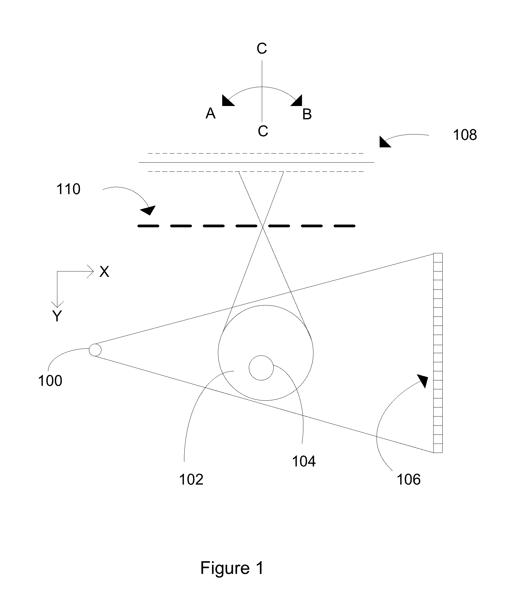
The present invention is a system, method, and apparatus for X-ray Compton scatter imaging. It uses two detectors in a volumetric CT system, one in line with the angle of attack of the incoming energy and another at a normal angle to the object being tested. The system also includes a Compton scattering subsystem with a second detector and a pin-hole collimator. The energy source directs energy along a path towards the object, and the first detector detects radiation. The Compton scattering subsystem measures the energy that passes through the pin-hole collimator, providing data related to interior features of the object. The system can be used in energy computed tomography imaging to provide data related to interior features of an object.

Problems solved by technology

Although the availability and usage of CT has increased dramatically over the last two decades, the increased use of X-rays has caused some concern.
Conventional x-ray CT imaging obtains the total linear attenuation coefficients from the three mechanisms mentioned above, and therefore does not provide an effective amount of patient information per dose.
This relative movement can severely degrade data acquisition efficiency.
These methods require an energy-sensitive detector, which is expensive using the current manufacturing technologies and is not available on commercial volumetric CT (VCT) systems.
Thus, conventional Compton imaging systems are either inefficient on dose and imaging time or require an energy-selective detector.

Method used


Image

  • X-ray compton scatter imaging on volumetric CT systems
  • X-ray compton scatter imaging on volumetric CT systems
  • X-ray compton scatter imaging on volumetric CT systems

Examples


Embodiment Construction

[0029]Although preferred embodiments of the invention are explained in detail, it is to be understood that other embodiments are contemplated. Accordingly, it is not intended that the invention is limited in its scope to the details of construction and arrangement of components set forth in the following description or illustrated in the drawings. The invention is capable of other embodiments and of being practiced or carried out in various ways. Also, in describing the preferred embodiments, specific terminology will be resorted to for the sake of clarity.

[0030]It must also be noted that, as used in the specification and the appended claims, the singular forms “a,”“an” and “the” include plural referents unless the context clearly dictates otherwise.

[0031]Also, in describing the preferred embodiments, terminology will be resorted to for the sake of clarity. It is intended that each term contemplates its broadest meaning as understood by those skilled in the art and includes all tech...


PUM


Abstract

Briefly described, in an exemplary form, the present invention discloses a system, method and apparatus for X-ray Compton scatter imaging. In one exemplary embodiment, the present invention uses two detectors in a volumetric CT system. A first detector is positioned generally in-line with the angle of attack of the incoming energy, or, generally in-line of path x, where x is the path of the incoming energy. The first, or primary, detector detects various forms of radiation emanating from an object undergoing testing. In some embodiments, the present invention further comprises a Compton scattering system positioned generally normal to path x. In some embodiments, the Compton scattering subsystem comprises a second detector and a pin-hole collimator. The second detector detects Compton scattering energy from the object being tested.

Description

CROSS REFERENCE TO RELATED APPLICATION[0001]This application claims benefit of U.S. Provisional Patent Application Ser. No. 61 / 514,246 filed 2 Aug. 2011, entitled, “X-Ray Compton Scatter Imaging on Volumetric CT Systems,” which application is hereby incorporated fully by reference.BACKGROUND OF THE INVENTION[0002]1. Field of the Invention[0003]The present invention relates generally to X-Ray Compton scatter imaging.[0004]2. Description of the Related Art[0005]Through the advancement of computing systems, conventional medical and industrial imaging systems provide an increased level of information available to the researcher. X-ray computed tomography can be used for medical imaging and industrial imaging methods employing tomography created by computer processing. A computed tomography (CT) scan can produce a large amount of data that can be manipulated, through a process known as “windowing”, in order to demonstrate various bodily structures based on their ability to block the X-ra...

Claims


Application Information

Patent Timeline
IPC IPC(8): G01N23/02G21K1/02A61B6/03
CPCG21K1/02G01N23/046A61B6/032A61B6/4078G01N2223/612A61B6/483G21K2207/005A61B6/508G01N2223/419A61B6/4233
Inventor ZHU, LEINIU, TIANYE
Owner GEORGIA TECH RES CORP
Learn More