Three-phase rotary machine control apparatus

a control apparatus and three-phase technology, applied in the direction of electric generator control, dynamo-electric converter control, dynamo-electric gear control, etc., can solve the problems of increasing torque ripple, affecting the operation of power converters, and limited current in one power supply system actually suffering from overheat, etc., to achieve the effect of suppressing torque ripple and overheat of power converters

Active Publication Date: 2013-02-07
DENSO CORP
View PDF4 Cites 40 Cited by
  • Summary
  • Abstract
  • Description
  • Claims
  • Application Information

AI Technical Summary

Benefits of technology

[0007]It is therefore an object to suppress torque ripple and overheat of power converters

Problems solved by technology

In this case, when the estimated temperature rises in one of the two power supply systems, the current will be limited only in one power supply system actually suffering from overheat.
As a result, the currents supplied in the two power supply systems differ and increase torque ripples.
Although shifting of phase of currents sup

Method used


Image

  • Three-phase rotary machine control apparatus
  • Three-phase rotary machine control apparatus
  • Three-phase rotary machine control apparatus

Examples


Embodiment Construction

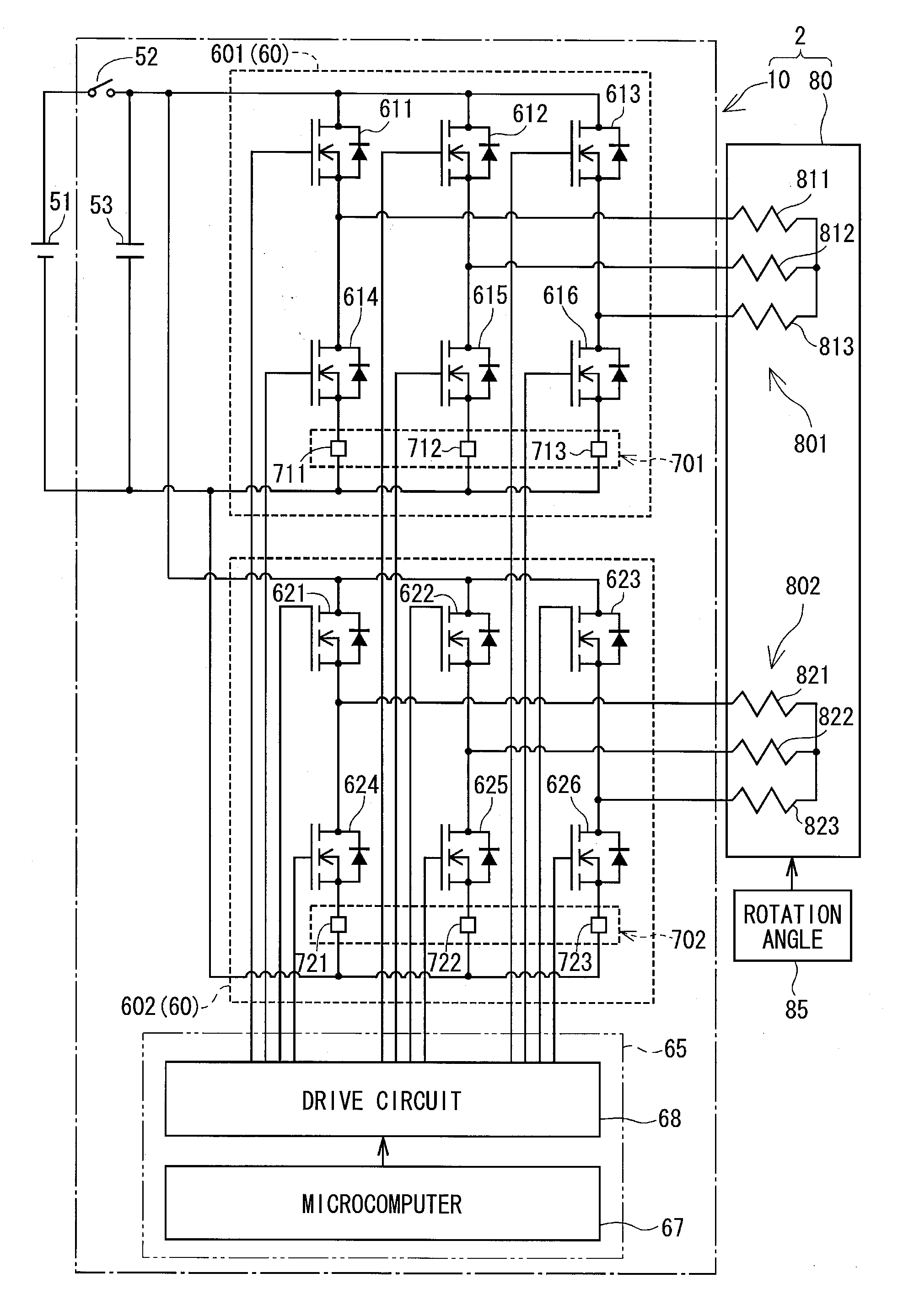
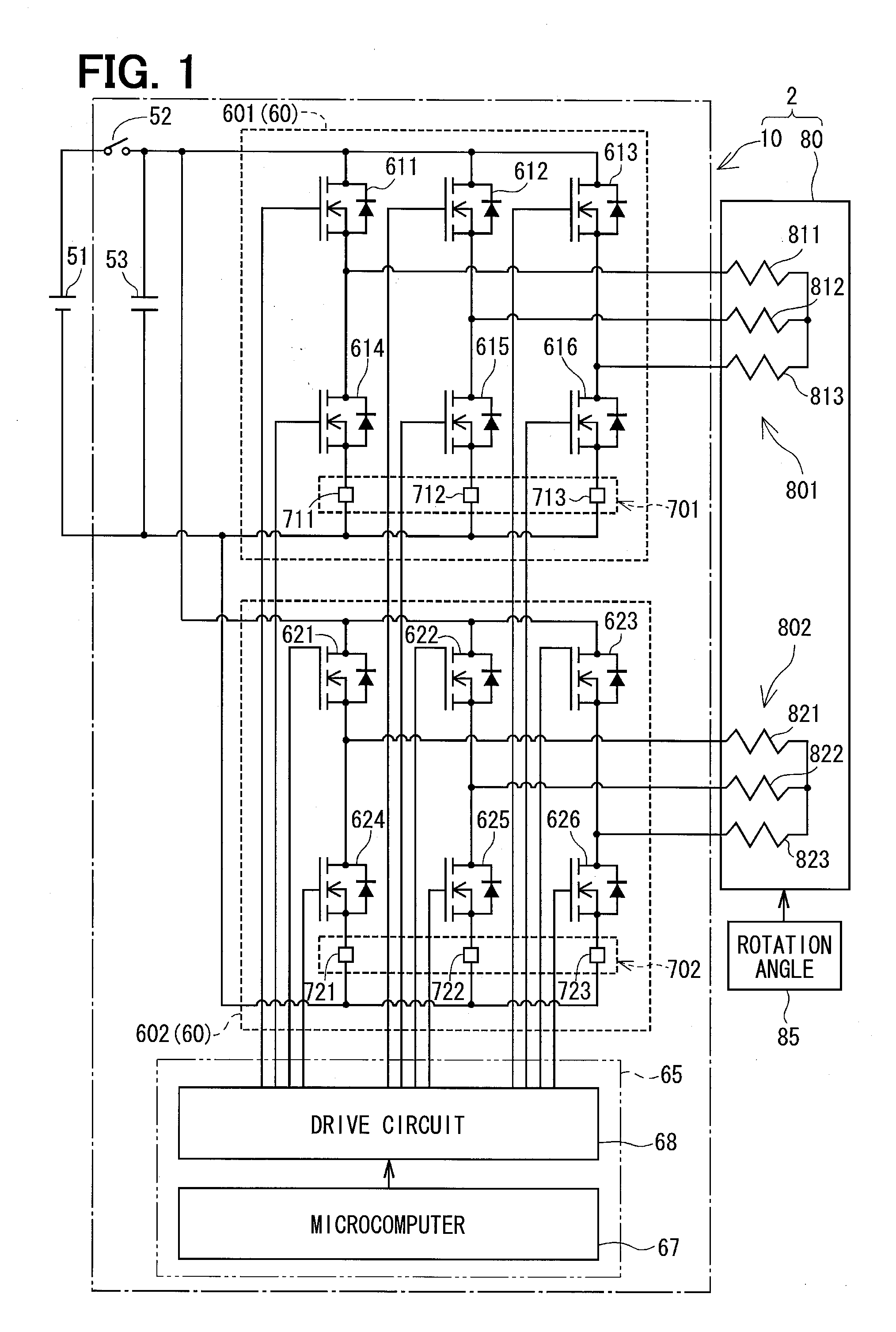
[0015]A control apparatus for controlling a three-phase rotary machine (three-phase rotary machine control apparatus) will be described with reference to one embodiment, in which the three-phase rotary machine control apparatus is implemented in an electric power steering system shown in FIGS. 1 and 2.

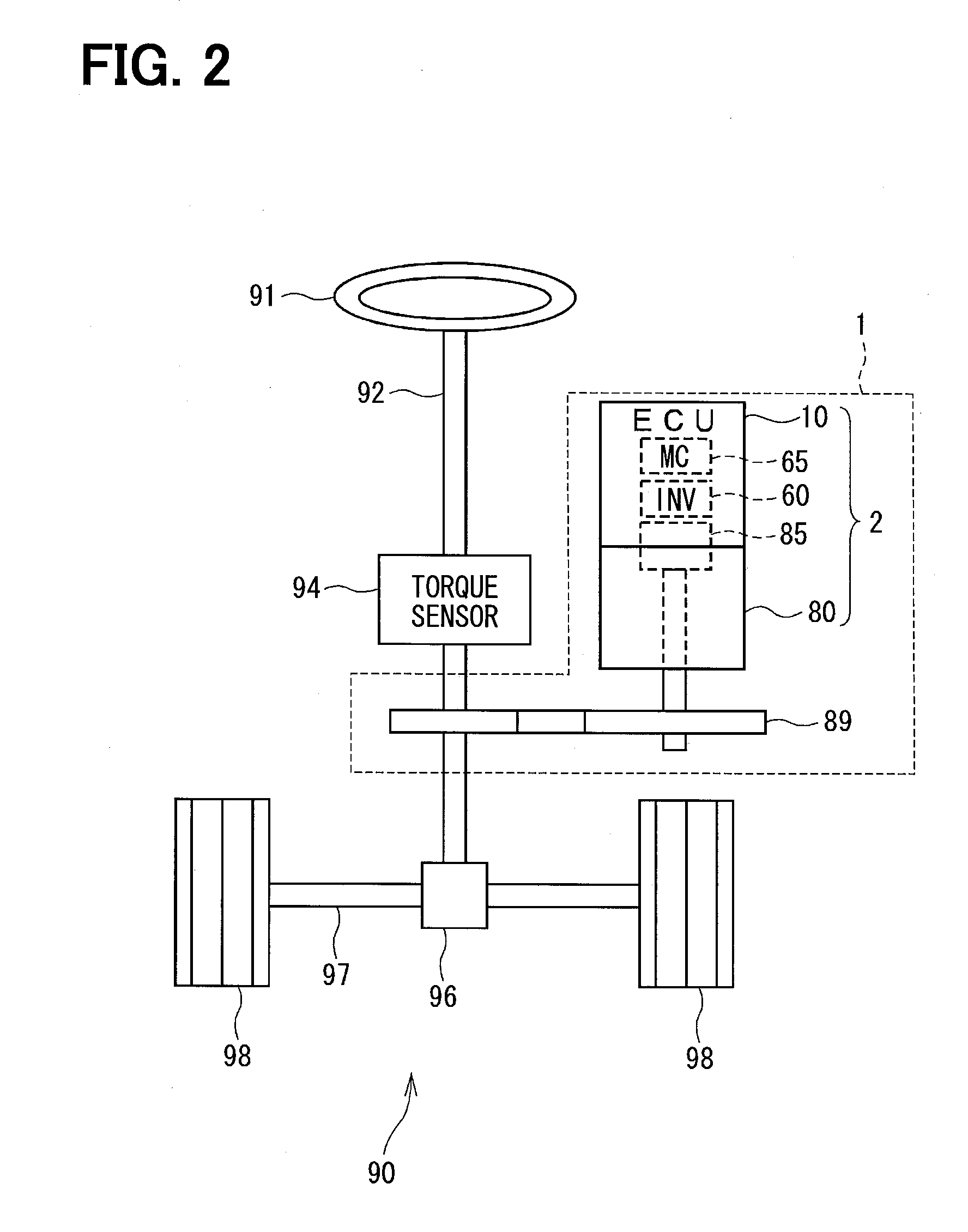
[0016]An electric power steering system 1 is provided in a steering system 90 of a vehicle as shown in FIG. 2. In this steering system 90, a torque sensor 94 is attached to a steering shaft 92 of a steering wheel 91 for detecting a steering torque. A pinion gear 96 is provided at a top end of the steering shaft 92 and engaged with a rack shaft 97. A pair of tire wheels 98 is coupled rotatably to both ends of the rack shaft 97 through tie rods and the like (not shown). The rotary motion of the steering shaft 92 is changed to the linear motion of the rack shaft 97 by the pinion gear 96 so that the pair of tire wheels 98 is steered by an angle corresponding to the linear motion of the rac...


PUM


Abstract

A first inverter and a second inverter supply two coil sets forming a three-phase motor with AC voltages, which are the same in amplitude but shifted by 30° in phase. Current detectors detect phase currents supplied from the inverters to the coil sets. Temperature estimation sections estimate temperatures of the inverters or the coil sets based on an integration value of the phase current detection values. A current command value limitation section limits upper limits of current command values of both coil sets based on the estimated temperatures Tm1 and Tm2. Thus, the inverters and the coils sets are protected from overheating without increasing torque ripple.

Description

CROSS REFERENCE TO RELATED APPLICATION[0001]This application is based on and incorporates herein by reference Japanese patent application No. 2011-168213 filed on Aug. 1, 2011.TECHNICAL FIELD[0002]The present invention relates to a three-phase rotary machine control apparatus.BACKGROUND ART[0003]Some conventional control apparatuses for controlling driving of a three-phase rotary machine include two power supply systems of power converters in correspondence to two three-phase coil sets, each of which includes three phase coils of a three-phase rotary machine.[0004]According to JP 02-70286A (patent document 1) corresponding to U.S. Pat. No. 4,814,964, for example, an AC motor drive apparatus is provided with two three-phase inverters for a motor, which has two coil sets angularly spaced apart by an angle of 30° from each other. Each coil set includes three phase coils. The two three-phase inverters are connected to the two coil sets of an AC motor, respectively. The two three-phase i...

Claims


Application Information

Patent Timeline
IPC IPC(8): H02P6/08B62D5/04B62D6/00H02M7/48H02P21/00H02P21/05H02P21/22H02P23/04H02P27/06H02P27/08
CPCH02P29/0055H02P6/002B62D5/0496B62D5/0403B62D5/046H02P21/0089H02P6/28H02P29/64
Inventor SUZUKI, TAKASHIHAYASHI, JIROU
Owner DENSO CORP
Why Eureka
Try Eureka