
System and methods for synchronizing edge devices on channels without carrier sense

a technology of edge devices and carrier sense, applied in the field of network resource management, can solve the problems of limiting the timing and frequency of messages from the ct to the icds, not being able to initiate contact with any icd, and not being able to broadcast to all icds at the same tim

Active Publication Date: 2013-02-07
DOMINION ENERGY TECH +1
View PDF6 Cites 43 Cited by
  • Summary
  • Abstract
  • Description
  • Claims
  • Application Information

AI Technical Summary

Benefits of technology

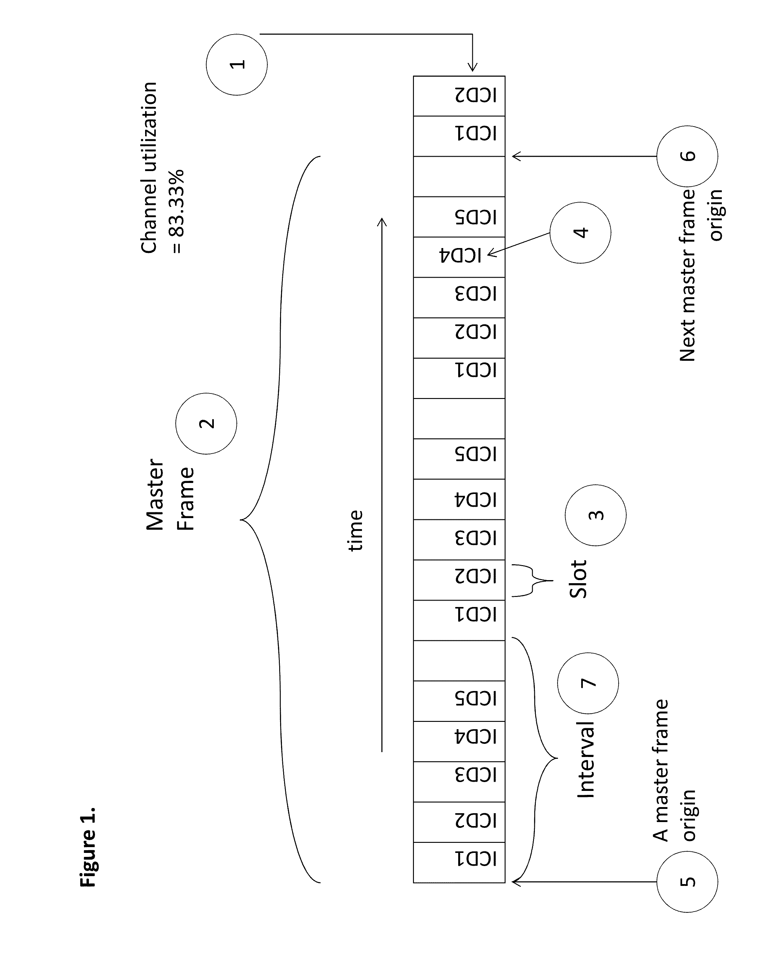
The present invention comprises a system of edge devices called Intelligent Communicating Devices (ICDs) that transmit using a slotted protocol according to a predefined or centrally assigned schedule, on a network typically lacking in carrier sense. The system includes a Server that controls a Central Transmitter (CT) which can send messages to the ICDs, and a CT of the second type that is not capable of broadcasting to all ICDs simultaneously and is limited to responding to contacts initiated by an ICD. The methods disclosed in the patent text allow for synchronization of the ICDs despite the constraints imposed by the characteristics of the CT type in use.

Problems solved by technology

CTs of the second type are typically not capable of broadcasting to all ICDs simultaneously, and are not capable of initiating contact with any ICD.
In both architectures constraints exist that limit the timing and frequency of messages from the CT to the ICDs.

Method used


Image

  • System and methods for synchronizing edge devices on channels without carrier sense
  • System and methods for synchronizing edge devices on channels without carrier sense
  • System and methods for synchronizing edge devices on channels without carrier sense

Examples


embodiment 1

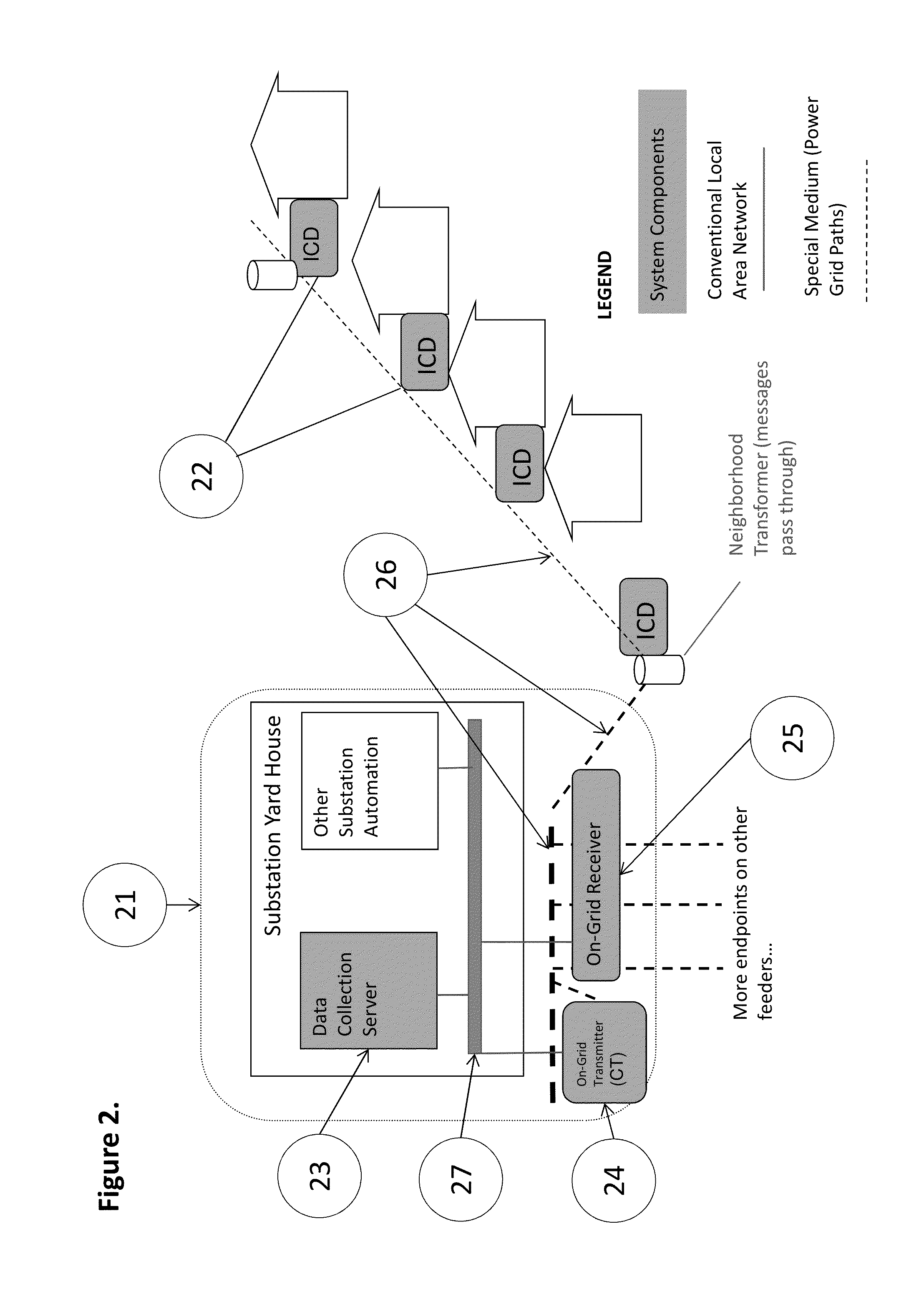
[0026]In a first embodiment of the invention, FIG. 2 illustrates an electrical distribution substation 21 from which originates an electrical distribution grid 26. The substation 21 contains a Server 23, a CT 24, and a Receiver 25. The Server has conventional two-way network communication with the CT and Receiver via Local Area Network 27. The network medium for the slotted edge to aggregation point transmissions used by the ICDs is the electrical distribution grid 26, and the network medium for transmission from the aggregation point to the edge is also the electrical distribution grid 26. At or near the edge of the electrical distribution grid are attached one or more ICDs 22. The one or more ICDs contain a system clock, a processor, storage for programs and data, and a transceiver capable of sending messages on the electrical distribution grid 26 to Receiver 25, and receiving messages sent by CT 24. The network medium provides at least one Edge-to-Aggregation point (E2A) channels...

embodiment 2

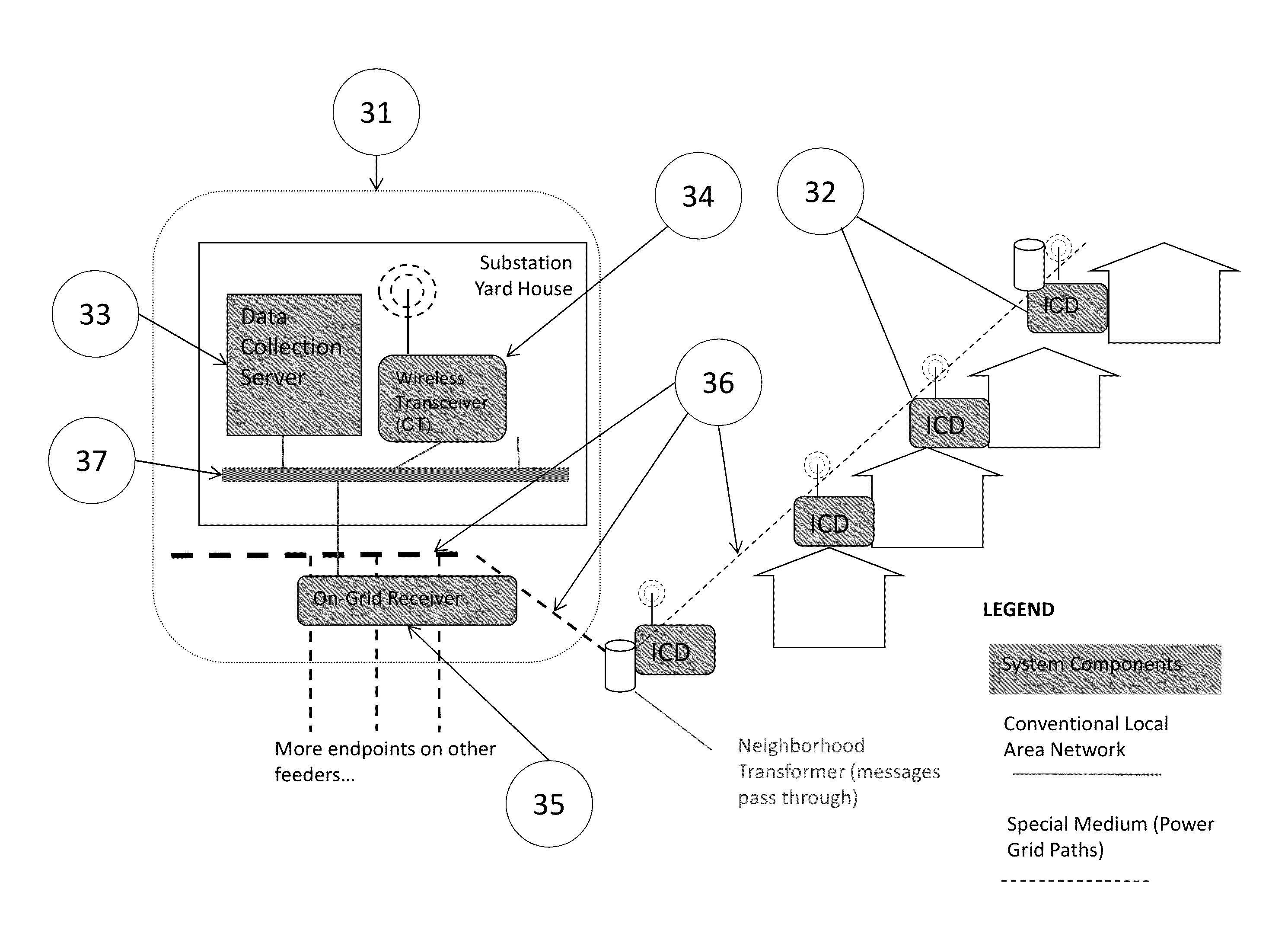
[0046]In a second embodiment of the invention, no in-band broadcast channel is available, and a third-party network provider is substituted to simulate the in-band CT and receivers at the ICD. This embodiment is called a simulated broadcast embodiment. FIG. 3 illustrates an electrical distribution substation 31 from which originates an electrical distribution grid 36. The substation 31 contains a Server 33, a wireless transceiver acting as the CT 34, and a Receiver 35. The Server has conventional two-way network communication with the CT and Receiver via Local Area Network 37. The network medium for the slotted edge to aggregation point transmissions used by the ICDs is the electrical distribution grid 36, and the network medium for transmission from the aggregation point to the edge is any conventional network that supports TCP / IP or other two-way communications protocols, but typically is a wireless network such as the cellular cloud, represented in FIG. 3 by the presence of anten...


PUM


Abstract

A system and method are disclosed for synchronizing edge devices on a network, wherein the network has limited bandwidth and does not support a practical carrier sense mechanism. The edge devices transmit, using a slotted protocol, to a server located at a central data aggregation point. The server also controls a Central Transmitter, which sends messages to the edge devices to assign transmission slots and provide timing information to the edge devices to ensure that transmissions sent by devices sharing the same communication channel do not collide.

Description

CROSS REFERENCE TO RELATED APPLICATIONS[0001]This application claims priority to U.S. Provisional Application No. 61 / 514,726, filed on Aug. 3, 2011 which is incorporated herein in its entirety.BACKGROUND OF THE INVENTION[0002]1. Field of the Invention[0003]The present invention is directed generally toward the domain of network resource management where the message bearing substrate for a multiplicity of transmitters sited at or near the edge of the network has limited bandwidth and does not support a practical carrier sense mechanism. An example of such a network is the electrical distribution grid. In such a network, if two or more transmitted messages overlap in time (collide) on the same bearer channel, neither message is decipherable at its destination. Slotted protocols, where every transmitter is allocated specific times wherein it is permitted to transmit, can maximize the utilization of such network. However, collisions are prevented only if the time clocks on every transmi...

Claims


Application Information

Patent Timeline
IPC IPC(8): H04L7/04H04W72/04H04W56/00
CPCH04W56/00H04L7/04H04L41/5022H04L47/6245H04W28/065H04W74/0891
Inventor MARTIN, MARCIA R.BERNHEIM, HENRICK F.ABENDSCHEIN, ANDREW LOUIS
Owner DOMINION ENERGY TECH
Learn More