Transparent optical interposer

a technology of transparent optical interposers and interposers, which is applied in the direction of optical elements, instruments, optical waveguide light guides, etc., can solve the problems of increasing the height of the interposer, and affecting the quality of the interposer

Inactive Publication Date: 2013-02-07
TE CONNECTIVITY CORP
View PDF7 Cites 9 Cited by
  • Summary
  • Abstract
  • Description
  • Claims
  • Application Information

AI Technical Summary

Benefits of technology

[0052]It should be apparent from the above description that the interposer assembly of the present invention provides for significant advantages over conventional electro-optic module configurations such as lower cost and simplicity in manufacturing and enhanced versatility with respect to the type of mating components with which it can effect optically coupling. Still other advantages of the interposer assembly are anticipated.

Problems solved by technology

Although an interposer configured with the optical conduit on one side and electronics on the other simplifies manufacturing, it does pose its own challenges.
Unfortunately, these light turning elements tend to be expensive to manufacture, and are relatively time consuming to incorporate onto the interposer as they must be both aligned and bonded to the substrate.
Consequently, these elements tend to be relatively bulky and add considerable height to the interposer.
This is particularly problematic because interposers are often used in space-restricted situations in which height must be minimized.
Thus, not only are the light turning elements expensive to prepare and complicated to install, but they also add undesirable height to the interposer.

Method used


Image

  • Transparent optical interposer
  • Transparent optical interposer
  • Transparent optical interposer

Examples


Embodiment Construction

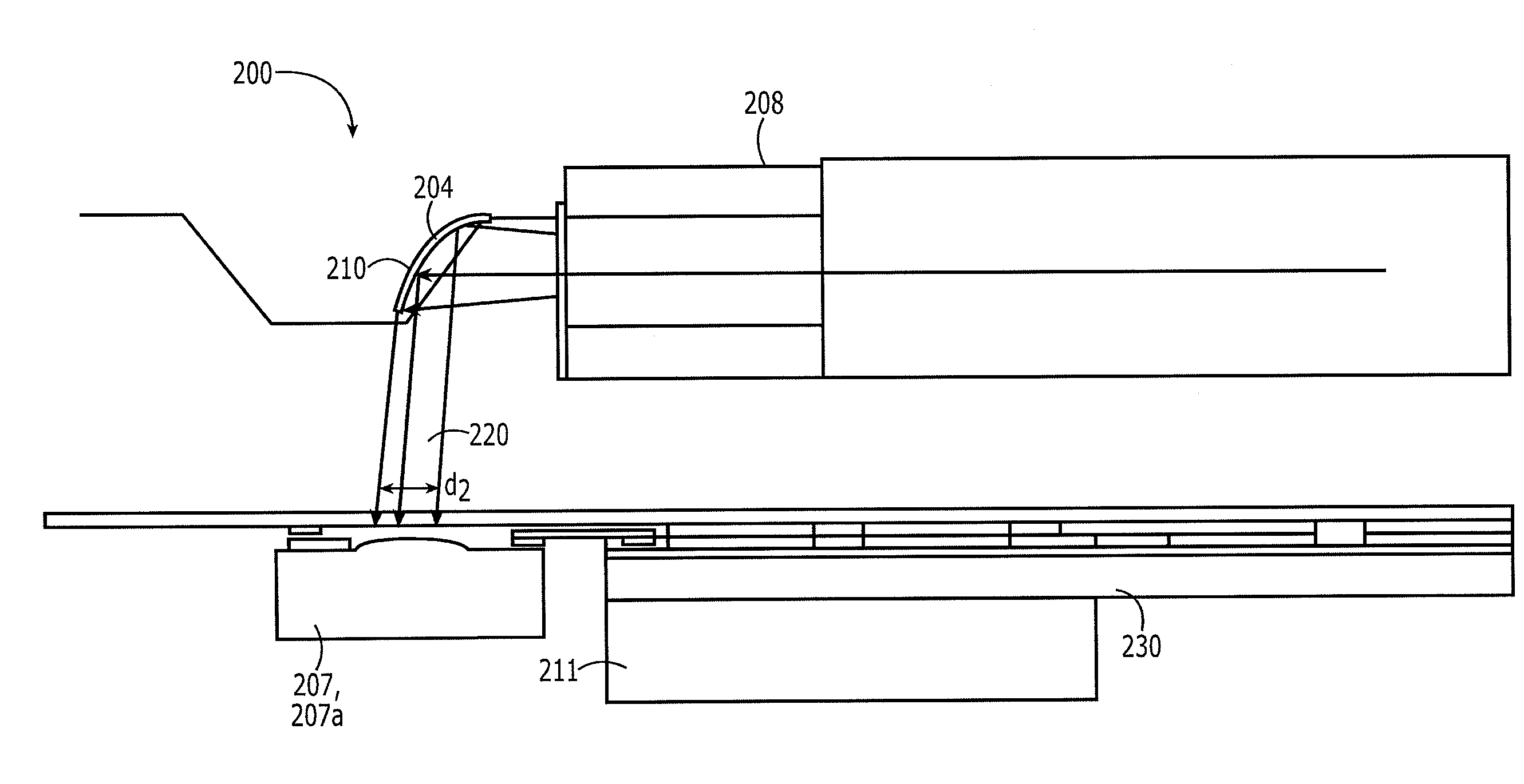
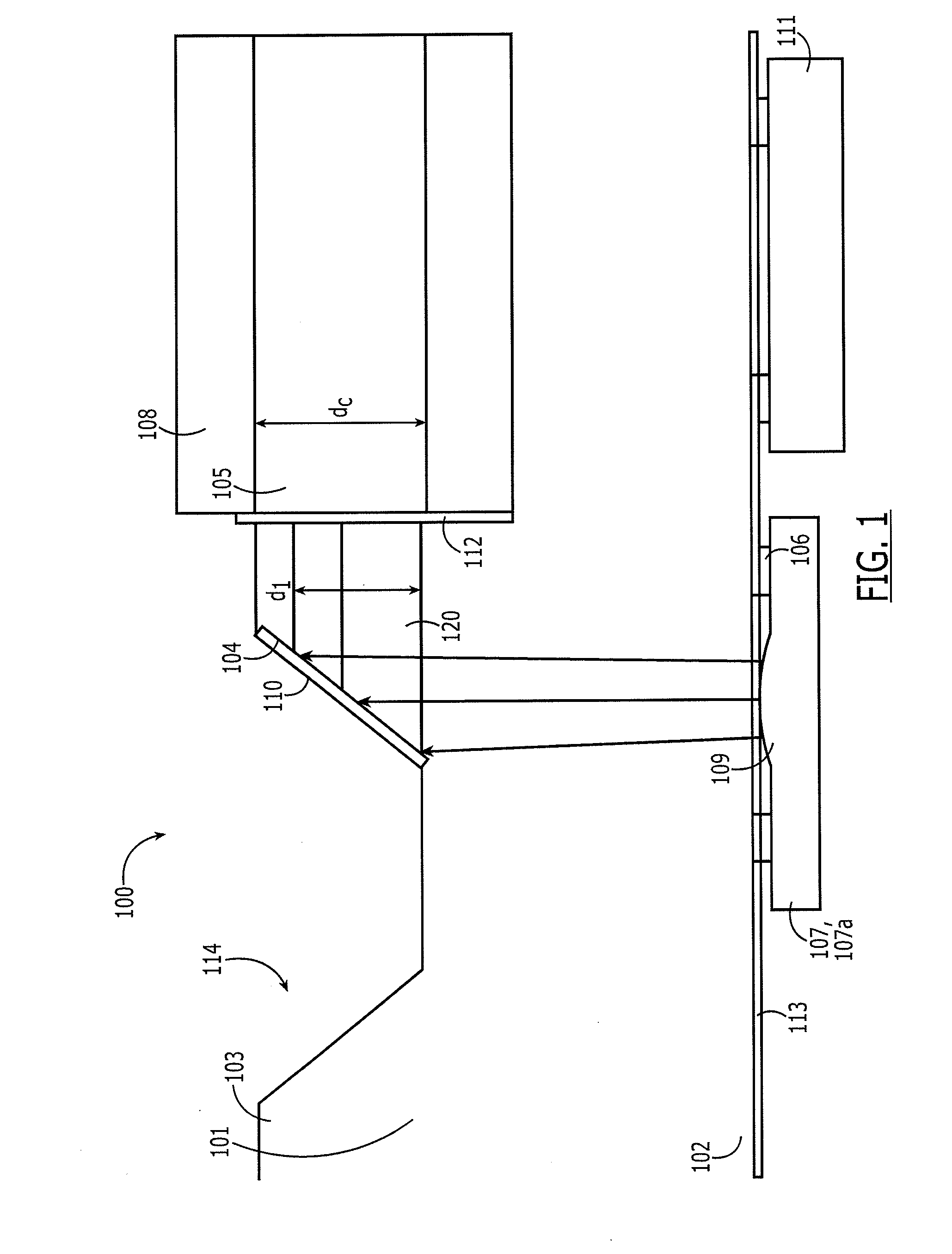
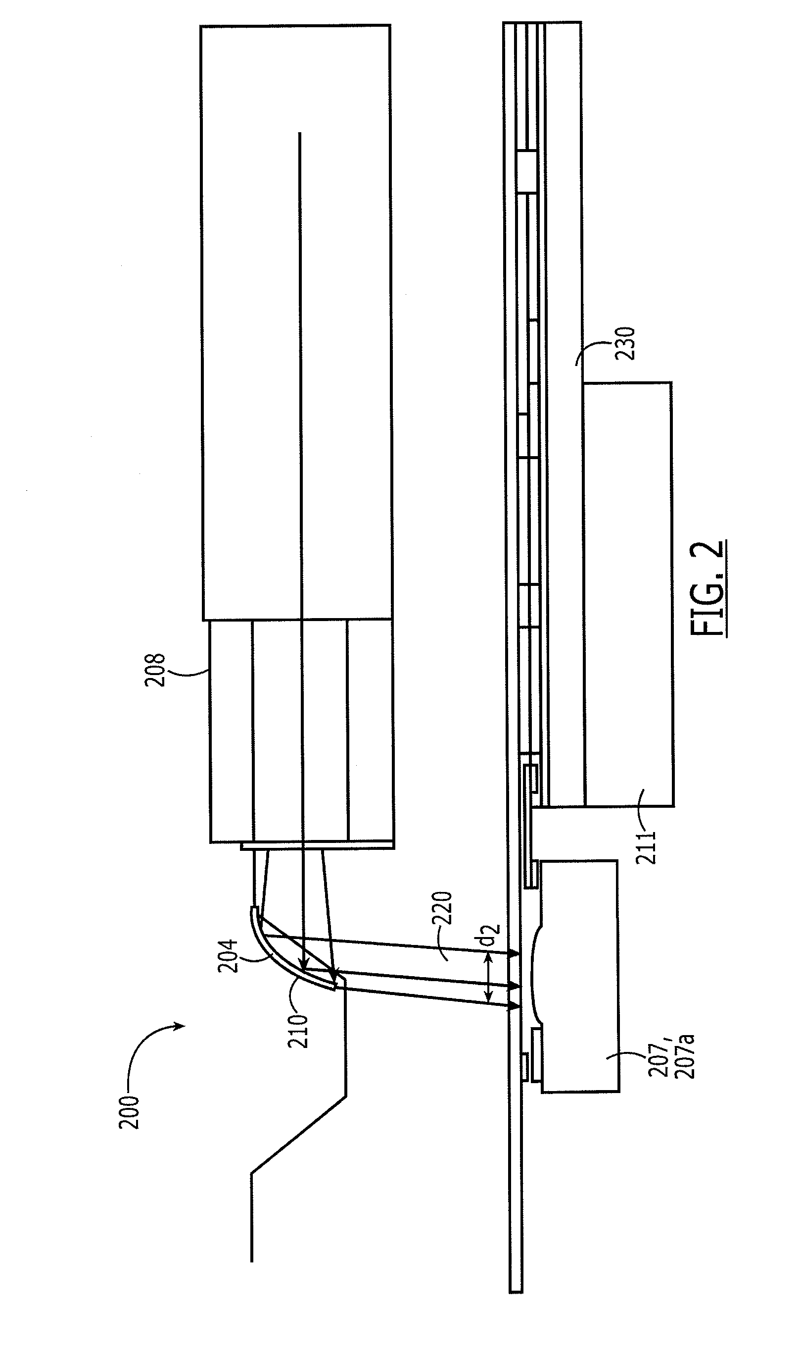
[0012]Referring to FIG. 1, one embodiment of the interposer 100 of the present invention is shown. The interposer 100 comprises a transparent substrate 101 having first and second sides 102, 103, respectively. The first side comprises electrical contact pads 106 and the second side defines at least one reflective surface 104 and at least one groove 105. At least one OED 107 is mounted to the electrical contact pads 106 on the first side. The groove 105 holds an optical conduit 108, which is optically coupled to said OED 107 by said reflective surface 104. Each of these elements is described in greater detail below.

[0013]The substrate 101 serves a number of purposes. Its primary purpose is to function as the backbone of the interposer to support and secure an optical conduit, OED(s) and supporting electrical circuitry. Accordingly, it should be a relatively rigid material that is thermally stable, suitable for being heated to temperatures typical in solder reflow applications. The su...


PUM

PropertyMeasurementUnit
angleaaaaaaaaaa
transparentaaaaaaaaaa
reflectivityaaaaaaaaaa

Abstract

An optical interposer comprising a transparent substrate having first and second sides, at least one OED mounted to the first side, at least one reflective surface and at least one groove defined on the second side, and an optical conduit disposed in the groove optically coupled to the OED by the reflective surface

Description

FIELD OF INVENTION[0001]The subject matter herein relates generally to fiber optic substrates, and more particularly, to a planar interposer with electrical components mounted on one side and optical components mounted on the opposite side.BACKGROUND OF INVENTION[0002]Fiber optic components are used in a wide variety of applications. The use of optical fibers as a medium for transmission of digital data (including voice, internet and IP video data) is becoming increasingly more common due to the high reliability and large bandwidth available with optical transmission systems. Fundamental to these systems are optical subassemblies for transmitting and / or receiving optical signals.[0003]Optical subassemblies typically comprise an interposer. As used herein, an interposer functions as a substrate for optical, opto-electrical, and electrical components and provides interconnections to optically and / or electrically interconnect the optical / opto-electrical / electrical components. Generally...

Claims


Application Information

Patent Timeline
Patent Type & Authority Applications(United States)
IPC IPC(8): G02B6/122H01R43/00
CPCG02B6/4214G02B6/43G02B6/136Y10T29/49117
Inventor BOWEN, TERRY PATRICK
Owner TE CONNECTIVITY CORP
Why Eureka
Try Eureka