
Diagnosis method and diagnosis apparatus for oil-filled electrical apparatus

a technology of diagnostic method and diagnostic apparatus, applied in chemical methods analysis, transformer/inductance cooling, instruments, etc., can solve the problems of low insulation performance, ineffective diagnosis technique of existing transformer, and unknown mechanism, and achieve the effect of correct evaluation

Inactive Publication Date: 2013-02-07
MITSUBISHI ELECTRIC CORP
View PDF2 Cites 2 Cited by
  • Summary
  • Abstract
  • Description
  • Claims
  • Application Information

AI Technical Summary

Benefits of technology

The invention provides a method to evaluate the risk of copper sulfide formation on the surface of a coil or other electrical apparatus. This is done by measuring dibenzyl disulfide, di-tert-butyl-p-cresol, or di-tert-butyl-phenol in the analysis of insulating oil collected from an existing electrical apparatus. This method is non-conventional and helps to accurately assess the risk of copper sulfide generation.

Problems solved by technology

This copper sulfide is a semiconductor, and hence insulating performance lowers when the same adheres to an insulator.
However, the details of the generation mechanism thereof are unknown, and there has existed no effective diagnosis technique for an existing transformer.
However, whether or not adhesion of copper sulfide reaches insulating paper has not been predictable even with this technique (PTL 1: Japanese Patent Laying-Open No. 2010-10439).
Further, there are a large number of methods diagnosing abnormal overheat or abnormal discharge by detecting a certain type of compound.
However, although the quantity or the like of copper sulfide generated in the oil-filled electrical apparatus e can be predicted when using the invention of NPL 1 or PTL 1, whether or not the generated copper sulfide adheres to insulating paper cannot be determined.
Although the invention of PTL 3 is a technique of diagnosing an anomaly of a transformer, the same does not allow determination of generation of copper sulfide.

Method used


Image

  • Diagnosis method and diagnosis apparatus for oil-filled electrical apparatus
  • Diagnosis method and diagnosis apparatus for oil-filled electrical apparatus
  • Diagnosis method and diagnosis apparatus for oil-filled electrical apparatus

Examples


first embodiment

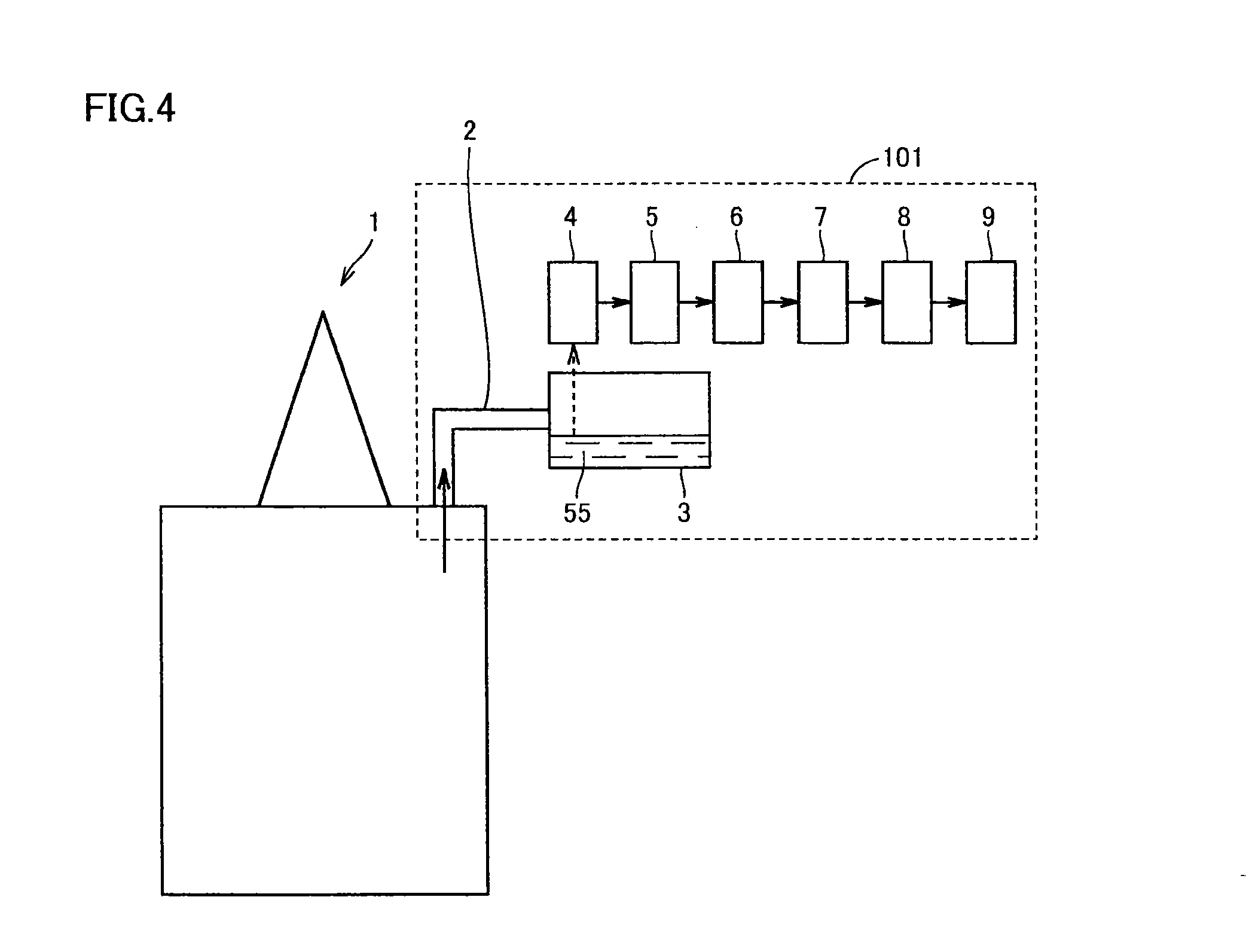
[0049]An embodiment of the diagnosis method for an oil-filled electrical apparatus according to the present invention is described. The diagnosis method according to this embodiment is a diagnosis method for an oil-filled electrical apparatus evaluating a risk of copper sulfide generation on an insulating paper surface of a coil or the like in the oil-filled electrical apparatus, and includes:

[0050]a first step of detecting a specific compound contained in insulating oil in the oil-filled electrical apparatus,

[0051]a second step of evaluating a possibility of copper sulfide generation in the said oil-filled electrical apparatus on the basis of the result of detection obtained in the said first step, and

[0052]a third step of diagnosing a risk of anomaly occurrence in the said oil-filled electrical apparatus on the basis of the result of evaluation obtained in the said second step.

[0053]More specifically, the possibility of copper sulfide generation in the oil-filled electrical appara...

second embodiment

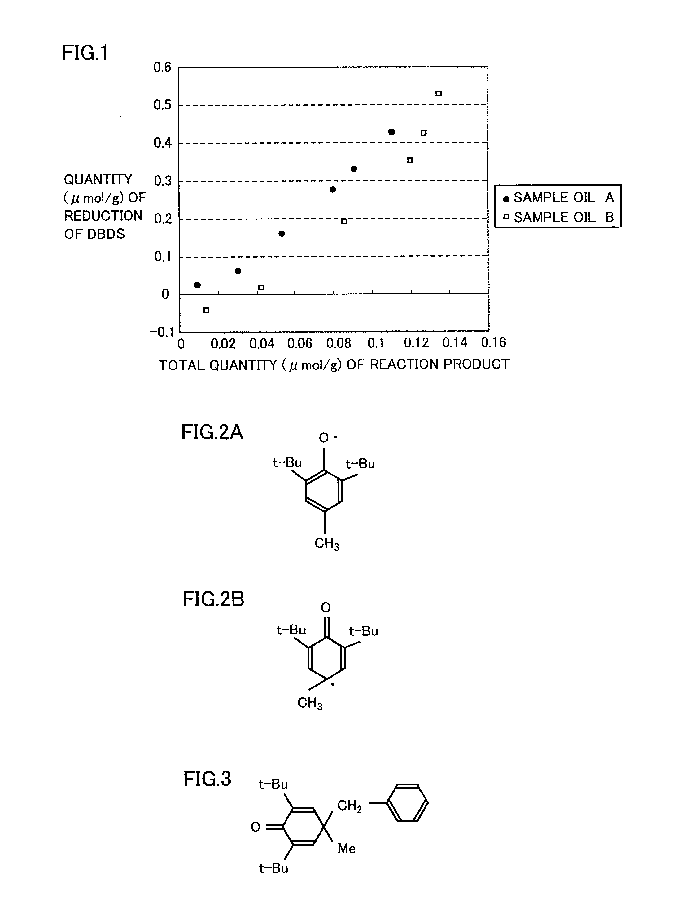
[0056]This embodiment is a diagnosis method different from the first embodiment in a point of measuring DBPC and a reaction product of a radical resulting from DBDS as the aforementioned specific compounds, and the remaining points are similar to those of the first embodiment.

[0057]DBDS and DBPC in insulating oil are gradually consumed due to use of the insulating oil in a transformer. Even in insulating oil having contained DBPC and DBDS before use, therefore, there is a case where DBDS and DBPC are not detected in a case of measuring only DBDS and DBPC after long-term use of the insulating oil. In such a case, there is a possibility that the transformer, which must be diagnosed as being at a high risk, is erroneously diagnosed as being at a low risk.

[0058]This embodiment can avoid such an erroneous determination by detecting a compound (reaction product of the radical resulting from DBDS) generated by consumption of DBDS in place of measurement of DBDS.

[0059]For example, benzaldeh...

third embodiment

[0063]This embodiment is a diagnosis method different from the first and second embodiments in a point of measuring a reaction product of a radical resulting from DBPC and a radical resulting from DBDS as the aforementioned specific compound, while the remaining points are similar to those of the first and second embodiments.

[0064]The measurement of the reaction product of the radical resulting from DBPC and the radical resulting from DBDS corresponds to measurement of “a specific compound containing a reaction product of a radical resulting from dibenzyl disulfide and a reaction product of a radical resulting from di-tert-butyl-p-cresol” in the diagnosis method according to the present invention. In other words, the detection of “the specific compound containing the reaction product of the radical resulting from dibenzyl disulfide and the reaction product of the radical resulting from di-tert-butyl-p-cresol” includes not only a case of detecting both of a reaction product of radica...


PUM


Abstract

Provided is a diagnosis method for an oil-filled electrical apparatus, which is for evaluating the degree of danger of copper sulfide being generated within the oil-filled electrical apparatus, comprising: a first step for detecting a specific compound contained within insulating oil inside the oil-filled electrical apparatus; a second step for evaluating the possibility of copper sulfide being generated inside the oil-filled electrical apparatus, on the basis of the result detected by the first step; and a third step for diagnosing the degree of danger of a malfunction occurring in the oil-filled electrical apparatus, on the basis of the evaluation result obtained in the second step. The specific compound contains dibenzyl disulfide and / or a reaction product of a radical resulting from dibenzyl disulfide, and di-tert-butyl-p-cresol and / or a reaction product of a radical resulting from di-tert-butyl-p-cresol, or, di-tert-butyl-phenol and / or a reaction product of a radical resulting from di-tert-butyl-phenol.

Description

TECHNICAL FIELD[0001]The present invention relates to anomaly diagnosis as to sulfidation corrosion of a transformer, and more detailedly, it relates to a technique of predicting generation of copper sulfide onto insulating paper.BACKGROUND ART[0002]Sulfidation corrosion is such a phenomenon that conductive copper sulfide is generated by reaction between copper which is the material for a transformer and a sulfur component in insulating oil. This copper sulfide is a semiconductor, and hence insulating performance lowers when the same adheres to an insulator. Insulating paper is used for coil insulation particularly in a large-sized transformer or the like, and hence a short circuit takes place between coils when copper sulfide adheres to this insulating paper which is an insulator, and the transformer is broken. However, the details of the generation mechanism thereof are unknown, and there has existed no effective diagnosis technique for an existing transformer.[0003]The inventors ...

Claims


Application Information

Patent Timeline
IPC IPC(8): G01N33/20G01N31/00
CPCG01N33/287H01F27/14Y10T436/182Y10T436/203332H01F27/402
Inventor TOYAMA, SATORUTANIMURA, JUNJIKATO, FUKUTAROAMIMOTO, TSUYOSHINAGAO, EIICHIKAWASHIMA, TAKESHIHOSOKAWA, NOBORU
Owner MITSUBISHI ELECTRIC CORP
Learn More