Appliance airflow detection using differential pressure sensing

a technology of differential pressure sensing and airflow detection, applied in the field of applications, can solve the problems of preventing the selected heating operation of the oven from proceeding, thermal switches have a relatively slow reaction time, thermal switches require a significant amount of calibration and testing, etc., and achieves the effect of avoiding calibration, fabrication and/or installation difficulties, and being convenient to install and calibra

Active Publication Date: 2013-02-07
HAIER US APPLIANCE SOLUTIONS INC
View PDF8 Cites 4 Cited by
  • Summary
  • Abstract
  • Description
  • Claims
  • Application Information

AI Technical Summary

Benefits of technology

[0006]The present disclosure provides for detecting air flow in a cooling air flow passageway of an appliance using solid-state flow detectors and controlling heat generating components of an appliance in response to detected air flow. More specifically, the disclosure provides a method and device for detecting the presence of airflow and/or the approximate rate of airflow in a cooling channel

Problems solved by technology

On the other hand, if the fan is not working properly, the FAD prevents the selected heating operation of the oven from proceeding.
However, the thermal switch has a relatively slow reaction time.
Moreover, the thermal switch requires a significant amount of calibration and testing to prove that it will work as intended in all working conditions of the oven.
However, the sail switch has its own limitations.
In particular, when it is desirable to direct or point the exhaust end or discharge end of the fan toward the floor on which the appliance is placed, it can be difficult to satisfactorily employ the sail switch in this configuration.
To make matters worse, in this

Method used


Image

  • Appliance airflow detection using differential pressure sensing
  • Appliance airflow detection using differential pressure sensing
  • Appliance airflow detection using differential pressure sensing

Examples


Embodiment Construction

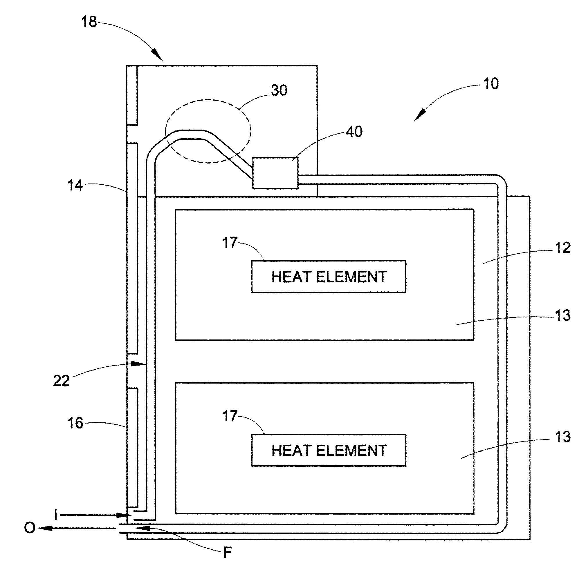
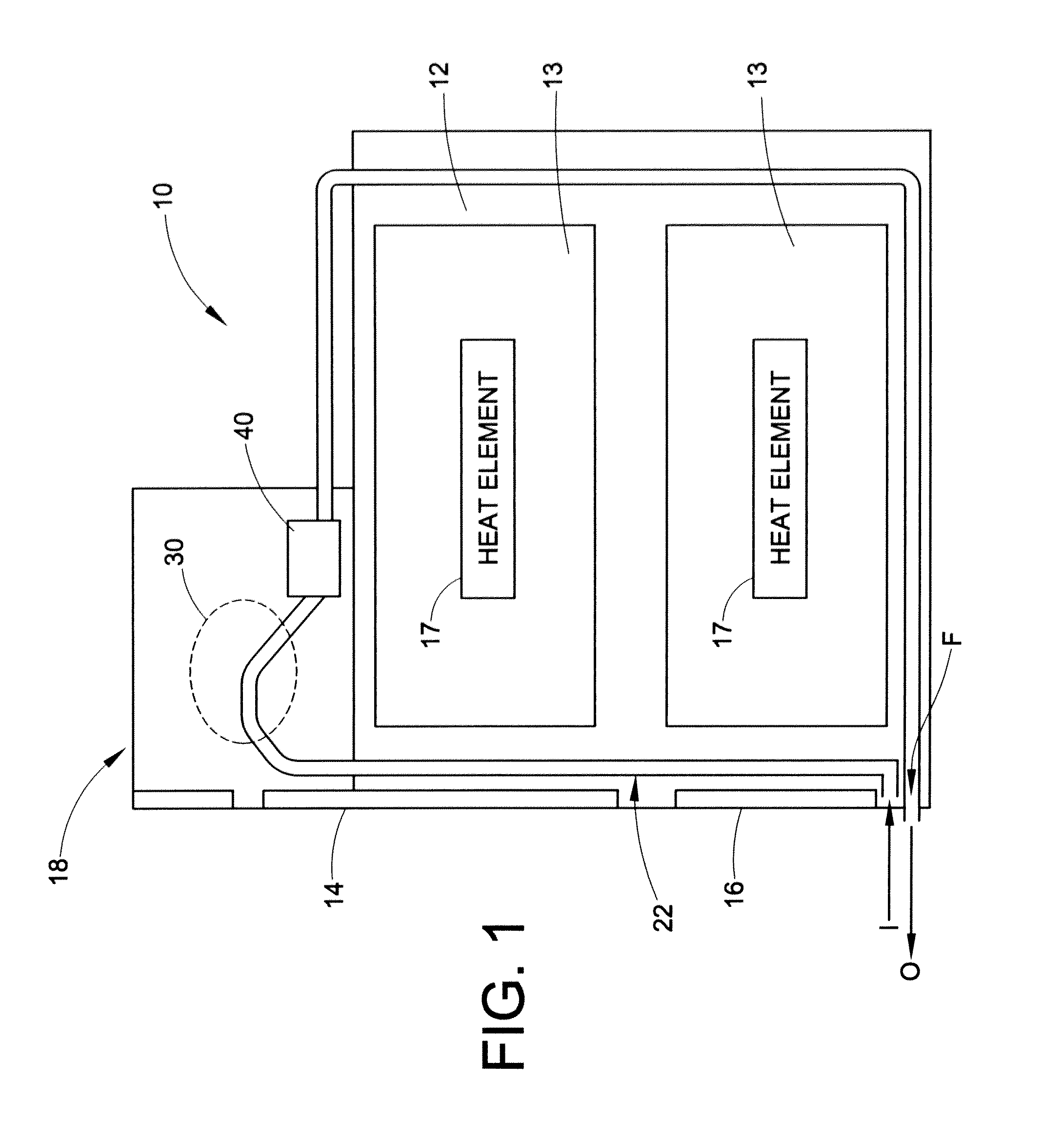
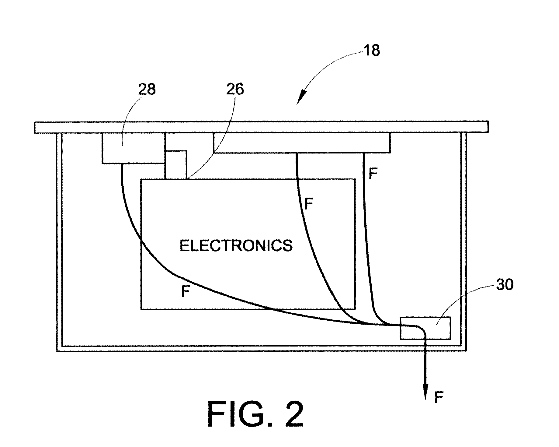
[0019]Turning now to the drawings, and initially to FIG. 1, an exemplary double wall oven 10 is illustrated. The double wall oven 10 generally includes an outer housing 12 defining an interior space 13 in which food or other items to be heated can be placed, and upper and lower doors 14 and 16 for providing access to respective portions of said interior space 13 inside of which one or more heating elements 17 are located. An electronics bay 18 is positioned on an upper side of the oven 10 and contains various electronic controls for controlling operation of the oven 10. It will be appreciated that the features of the present disclosure can be implemented in a wide variety of appliances and, thus, the specific type of oven or appliance is merely exemplary. Accordingly, only the basic features of the oven 10 are described.

[0020]As is conventional, the oven 10 includes one or more cooling air-flow passageways 22 for circulating air around the oven chassis and the electronics bay 18. Th...


PUM


Abstract

A device for detecting and/or measuring air flow in a cooling air flow passageway of an appliance using solid-state flow detectors. Heat generating components of the appliance are controlled in response to detected air flow. More specifically, the disclosure provides a device for detecting the presence of airflow and/or the approximate rate of airflow in a cooling channel of an appliance chassis. Based on this information, the appliance can perform safety-related tasks, such as de-energizing associated heating elements if there is too-low (or no) airflow detected. The solid-state flow detectors are easily fabricated, installed, and calibrated and avoids the calibration, fabrication and/or installation difficulties associated with sail switches and other such approaches such as thermal limit switches.

Description

BACKGROUND OF THE DISCLOSURE[0001]The present disclosure generally relates to appliances, and more particularly, to detecting airflow, and / or measuring airflow velocity, in a cooling pathway of an appliance.[0002]Appliances such as cooking ranges are widely used. A cooking range typically includes an oven. The oven typically has a front-opening access door, and at least one heating element for heating up the inside of the oven cavity. As is known in the art, when energized, the heating element can heat up the inside of the oven cavity to a relatively high cooking temperature chosen by a user. Also as is known in the art, the cooking range often has a fan which is used to cool a component of the oven, such as the front-opening access door, or a heat sensitive component of the oven such as an electrical element (e.g., electronic controller, display unit, etc.), to a temperature which is lower than the chosen cooking temperature. Some certification institutions, such as Underwriters La...

Claims


Application Information

Patent Timeline
IPC IPC(8): F24F11/00
CPCF24F11/00F24C15/006G01F11/44G01F1/34
Inventor BACH, JAMES CARTERNEWSOM, PAUL E.
Owner HAIER US APPLIANCE SOLUTIONS INC
Why Eureka
Try Eureka