Plastic-made nozzle cap

a nozzle cap and plastic technology, applied in the field of plastic-made nozzle caps, can solve the problems of syringe nozzles that also have to rely on rubber elasticity and frictional resistance, and the component is more difficult to maintain sealing performance than the piston, so as to achieve high sealing performan

Inactive Publication Date: 2013-02-07
DAIKYO SEIKO LTD
View PDF5 Cites 2 Cited by
  • Summary
  • Abstract
  • Description
  • Claims
  • Application Information

AI Technical Summary

Benefits of technology

The patent is about a plastic-made nozzle cap for a plastic syringe that can be securely connected to a female Luer lock fitting of the syringe and maintain a high sealing performance even when used repeatedly. The cap provides a solution to the problem of plastic nozzle caps that can easily crack or become less effective at sealing over time.

Problems solved by technology

Under such conditions, the constituent material of a prefilled syringe, to say nothing of its medicine itself, cannot avoid a volumetric expansion or shrinkage, and the rate of expansion or shrinkage differs depending on the material.
As opposed to the piston slidably inserted in the syringe barrel, the nozzle cap has such a shape as covering the nozzle of the syringe barrel from the outside, and is a component that is more difficult to maintain sealing performance than the piston.
From the standpoint of providing still more improved sealing performance, however, the above-described nozzle caps made of the rubber-based material s are excellent in sealing performance owing to the rubber elasticity of the rubber-based materials, but on the other hand, are accompanied by a problem that their connection with the associated syringe nozzles has to also rely upon rubber elasticity and frictional resistance.
Nonetheless, the addition of a thermoplastic elastomer as much as from 20 to 50 wt % is needed to impart sufficient elasticity for the assurance of flexibility, in other words, the sealing performance for the nozzle caps, so that a new problem has arisen as will be described hereinafter.
The use of a resin material with such a large amount of an elastomer contained therein may raise another problem in that dissolved matter from the elastomer cannot be avoided completely.
In this case, the sealing performance is impaired.

Method used


Image

  • Plastic-made nozzle cap
  • Plastic-made nozzle cap
  • Plastic-made nozzle cap

Examples


examples 1 and 2

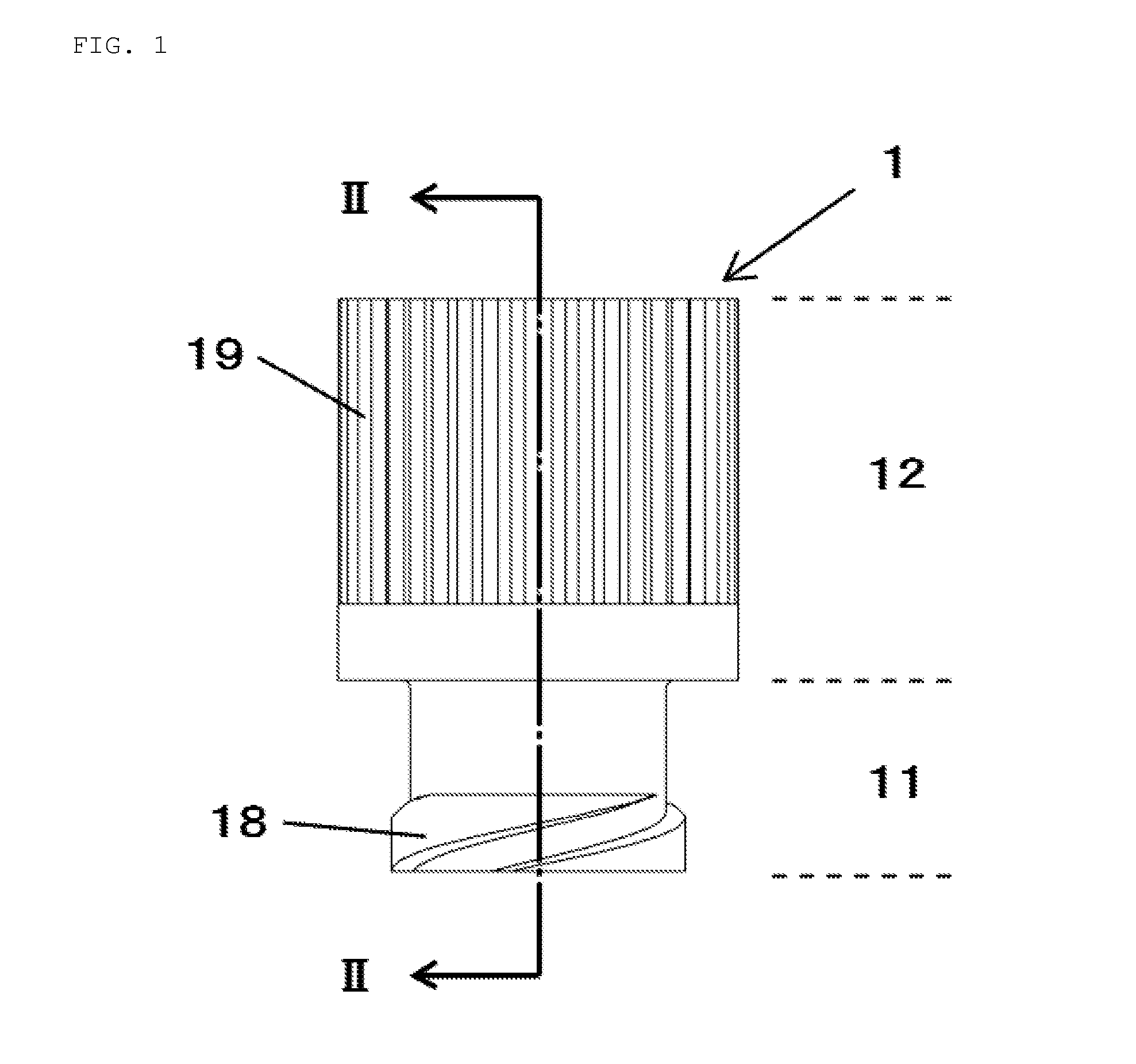
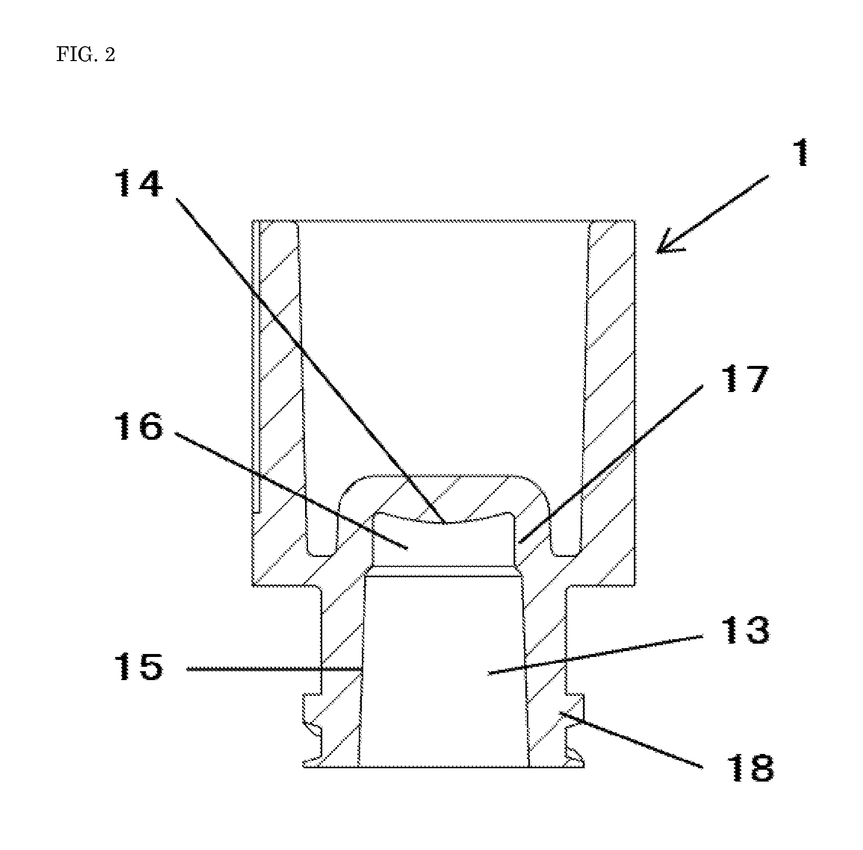
[0033]Using polymethylpentene (”DX845”, trade name, product of Mitsui Chemicals, Inc.), nozzle caps of the structure shown in FIG. 2 were produced by injection molding. They were provided as the nozzle caps of Example 1. They had the following dimensions—the outer diameter of a finger knob for attachment / detachment: approx. 10 mm, the length of the finger knob for attachment / detachment: approx. 10 mm, the diameter of an outer circumference of a leg section: approx. 7 mm, the length of the outer circumference of the leg section: approx. 5 mm, the diameter of a cavity on the side of its opening: approx. 4.8 mm, the diameter of the cavity on the side of a cavity top wall: approx. 4.3 mm, the depth of the cavity: approx. 7 mm, the inner diameter of a ring-shaped guide: 3.9 mm (uniform diameter), the length of the ring-shaped guide: 1.5 mm, and the radius of curvature of a cavity top wall portion: 5.0 mm. In a similar manner as in Example 1 except for the omission of the ring-shaped guid...

example 3

[0034]In a similar manner as in Example 1 except for the replacement of the ring-shaped guide in each nozzle cap by the protrusion-shaped guides depicted in FIG. 3, nozzle caps were produced and provided as the nozzle caps of Example 3. The dimensions and the like of the protrusion-shaped guides were set as in the second embodiment.

examples 4 to 7

[0035]In a similar manner as in Example 2 except that the radius of curvature of the cavity top wall portion of each nozzle cap was changed to 0.6, 1.3, 8.1 and 12.0 mm, respectively, nozzle caps were produced. Those nozzle caps were provided as the nozzle caps of Examples 4 to 7, respectively.


PUM


Abstract

A plastic-made nozzle cap for a plastic syringe includes a leg section, a cavity top wall portion, and a finger knob for the attachment / detachment of the nozzle cap. The leg section is structured for connection with a female Luer lock fitting formed face-to-face with an outer circumferential wall of a syringe nozzle. The cavity top wall portion is provided with a curved surface having a downwardly-convex, radius of curvature ranging from 0.6 to 12.0 mm for being brought into contact with a tip of the syringe nozzle to maintain sealing performance. The finger knob is arranged on an upper side of the leg section, and extends above the female Luer lock fitting in a state that a syringe barrel and the nozzle cap have been connected together.

Description

CROSS-REFERENCE TO RELATED APPLICATION[0001]This application claims the priority of Japanese Patent Application 2011-171674 filed Aug. 5, 2011, which is incorporated herein by reference.BACKGROUND OF THE INVENTION[0002]1. Field of the Invention[0003]This invention relates to a plastic-made nozzle cap for a plastic syringe useful with a medicine, and specifically, to a plastic-made nozzle cap that can be firmly connected to a female Luer lock fitting of such a syringe and can also maintain high sealing performance.[0004]2. Description of the Related Art[0005]Prefilled syringes useful as combined container-syringe units for medicines have been finding an ever-increasing demand for their convenience in recent years. A prefilled syringe is generally constructed of a substantially cylindrical syringe barrel, a substantially cylindrical piston, a plunger rod, and a substantially cylindrical nozzle cap. The syringe barrel is provided at an end thereof with a nozzle formed for the attachmen...

Claims


Application Information

Patent Timeline
Patent Type & Authority Applications(United States)
IPC IPC(8): A61M5/32
CPCA61M5/31A61M2005/3104A61M39/20
Inventor KAWAMURA, HIDEAKI
Owner DAIKYO SEIKO LTD
Why Eureka
Try Eureka