
Method and apparatus for generating a tool path for a robotic orthopedic surgical procedure

Active Publication Date: 2013-02-07
THINK SURGICAL
View PDF1 Cites 51 Cited by
  • Summary
  • Abstract
  • Description
  • Claims
  • Application Information

AI Technical Summary

Benefits of technology

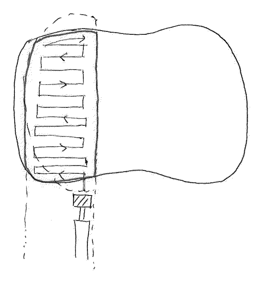
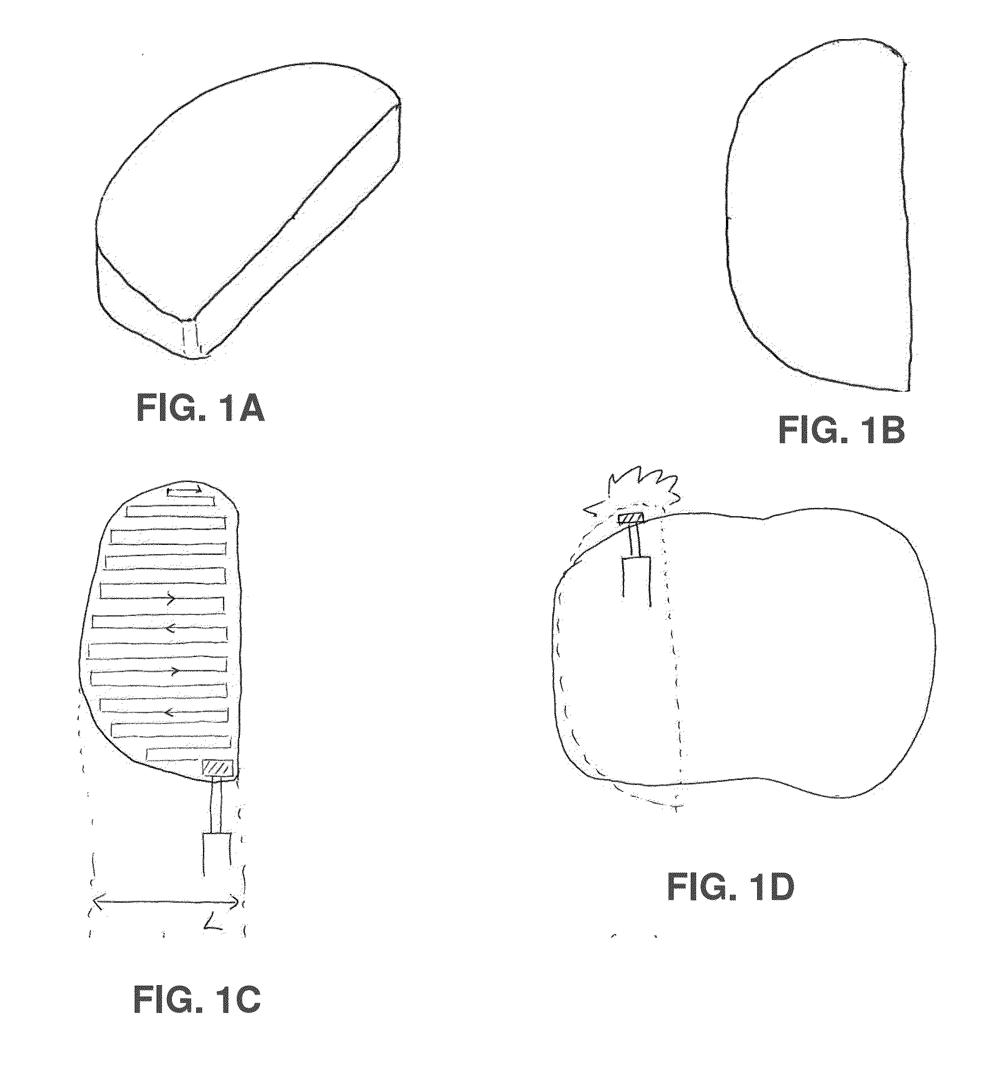
The present invention provides a method and apparatus for improving tool path generation for an implant. The method involves accessing an image of the bone to be cut and the desired cutting pattern, calculating the intersection of these two images, and generating the tool path based on this intersection. The goal is to minimize soft tissue trauma by reducing bone overcut, minimizing the required surgical access, and leaving a thin perimeter of bone at the boundary of the bone cut. The tool path is generated based on surgical access, can be optimized to reduce the size of the surgical opening, and can be designed to act as a protective wall to prevent contact with soft tissue. The apparatus includes a virtual model of the bone and pre-determined cutting pattern, which are used to generate the tool path.

Problems solved by technology

By way of example but not limitation, if the pre-programmed tool path is not customized for each patient, there is the possibility that the bone may be overcut.
Thus, the cutter can cause damage to soft tissue (or other anatomical structures) surrounding the bone.
At the same time, the use of conventional metal protectors, which is common in manual surgery, is problematic in robotic surgery because, if the cutter collides with the metal protector, the cutter and protector may be damaged and may leave metal debris in the patient's body.
Furthermore, during typical robotic surgery, there is generally insufficient room to accommodate a metal protector due to the presence of the robot tool or robot arm.

Method used


Image

  • Method and apparatus for generating a tool path for a robotic orthopedic surgical procedure
  • Method and apparatus for generating a tool path for a robotic orthopedic surgical procedure
  • Method and apparatus for generating a tool path for a robotic orthopedic surgical procedure

Examples


Embodiment Construction

[0054]The present invention provides a novel method and apparatus for generating an improved tool path for an implant which minimizes soft tissue trauma, e.g., by utilizing a pre-determined tool path but also protecting the soft tissues behind or around the bone, and also minimizing the required surgical access.

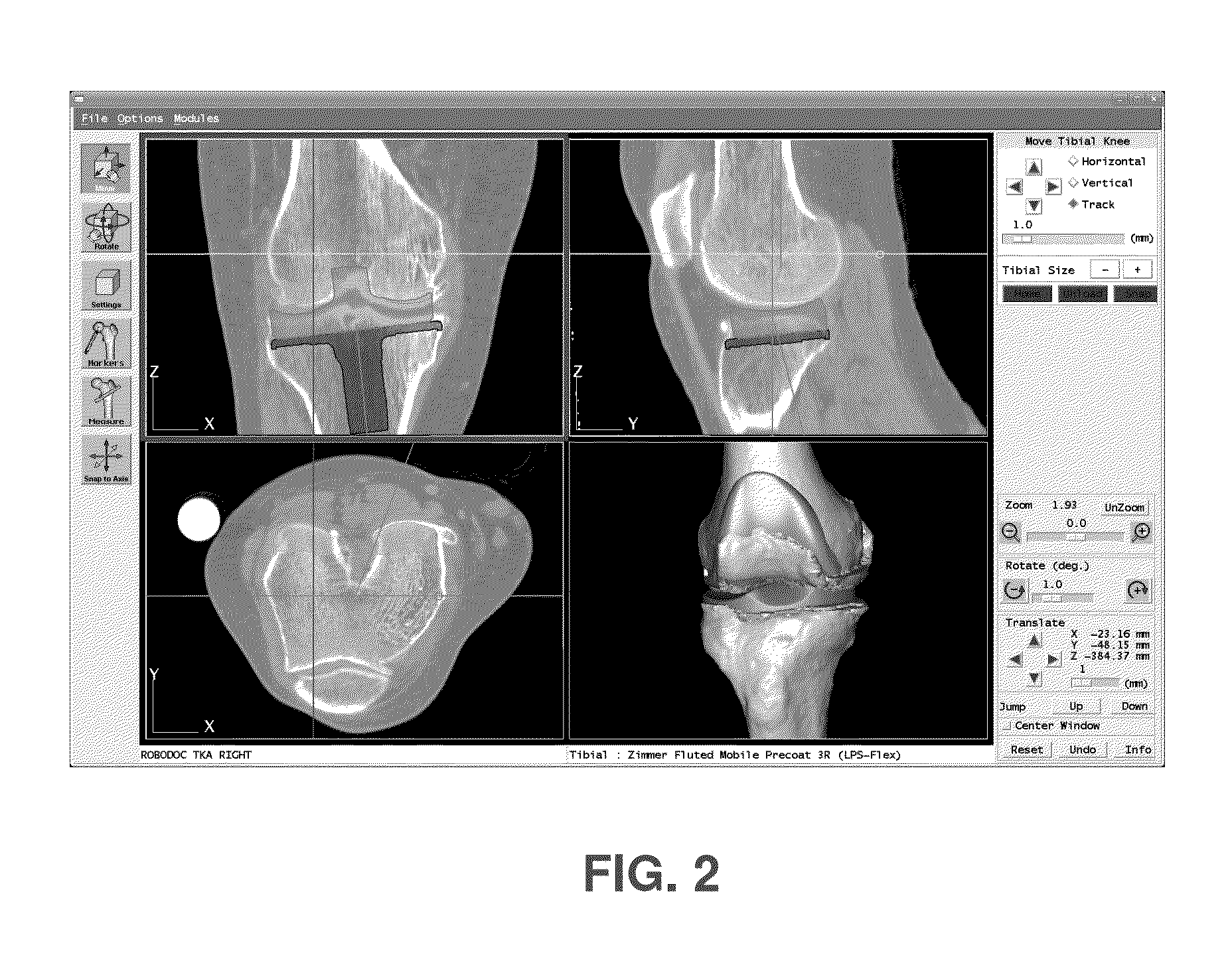
[0055]In accordance with the present invention, this is done by using pre-operative surgical planning software (FIG. 2) to access an image of the bone which is to be cut and to access an image of the desired cut (i.e., the pre-determined cutting pattern) which is to be made in the bone. The pre-determined cutting pattern is a combination of the volume or surface which will be cut by the surgical robot, as well as containing a template of the pre-determined tool path for that volume or surface. The image of the cutting pattern is placed over the image of the bone. Then the intersection of the cutting pattern and the bone is calculated. Based upon this intersection, a tool path...


PUM


Abstract

A method for generating an improved tool path for cutting a bone so as to minimize soft tissue trauma, wherein the method comprises:accessing an image of the bone which is to be cut;accessing an image of a pre-determined cutting pattern;superimposing the image of the pre-determined cutting pattern against the image of the bone;calculating the intersection of the pre-determined cutting pattern and the bone using the superimposed images of the pre-determined cutting pattern and the bone; andgenerating a tool path based upon the intersection of the pre-determined cutting pattern and the bone so as to minimize soft tissue trauma by leaving a thin perimeter of bone at the boundary of the bone cut when the boundary of the bone cut is adjacent to a bone surface.

Description

REFERENCE TO PENDING PRIOR PATENT APPLICATION[0001]This patent application claims benefit of pending prior U.S. Provisional Patent Application Ser. No. 61 / 499,572, filed Jun. 21, 11 by Brent Mittelstadt for TOOL PATH GENERATION METHOD FOR A ROBOTIC ORTHOPEDIC PROCEDURE (Attorney's Docket No. CUREXO-4 PROV), which patent application is hereby incorporated herein by reference.FIELD OF THE INVENTION[0002]This invention relates to pre-operative surgical planning software for robotic orthopedic surgical procedures, and more particularly to a novel method and apparatus for producing a patient-specific tool path for shaping bone during a robotic orthopedic surgical procedure.BACKGROUND OF THE INVENTION[0003]In an orthopedic surgical procedure which requires the cutting or shaping of bone, achieving higher accuracy in cutting or shaping the bone can yield superior surgical outcomes. To this end, orthopedic surgical robots such as the ROBODOC® surgical assistant system (Curexo Technology Cor...

Claims


Application Information

Patent Timeline
IPC IPC(8): A61B17/17G06K9/36G16H20/40G16H30/40
CPCA61B17/17G06K9/36G06T7/0012A61B17/1626A61B19/2203G06F19/3481A61B2017/1602A61B2019/505A61B2019/507G06F19/3437A61B19/50A61B34/30A61B34/10A61B2034/105A61B2034/107G16H50/50G16H20/40G16H30/40G06V10/20
Inventor MITTELSTADT, BRENTPARK, YOUNGBAE
Owner THINK SURGICAL
Learn More