Vision correction method for tool center point of a robot manipulator

a robot manipulator and tool center technology, applied in the direction of electric programme control, program control, instruments, etc., can solve the problems of time-consuming and inconvenient manual process, inability to guarantee the correction accuracy, and the tcp to deviate from the expected position

Active Publication Date: 2013-02-07
CLOUD NETWORK TECH SINGAPORE PTE LTD +1
View PDF20 Cites 34 Cited by
  • Summary
  • Abstract
  • Description
  • Claims
  • Application Information

AI Technical Summary

Problems solved by technology

Since the tool may have been mounted to the distal end of the robot manipulator manually, an alignment error may arise between the tool and the robot manipulator, causing the TCP to deviate from its expected position.
This is a t

Method used


Image

  • Vision correction method for tool center point of a robot manipulator
  • Vision correction method for tool center point of a robot manipulator
  • Vision correction method for tool center point of a robot manipulator

Examples


Embodiment Construction

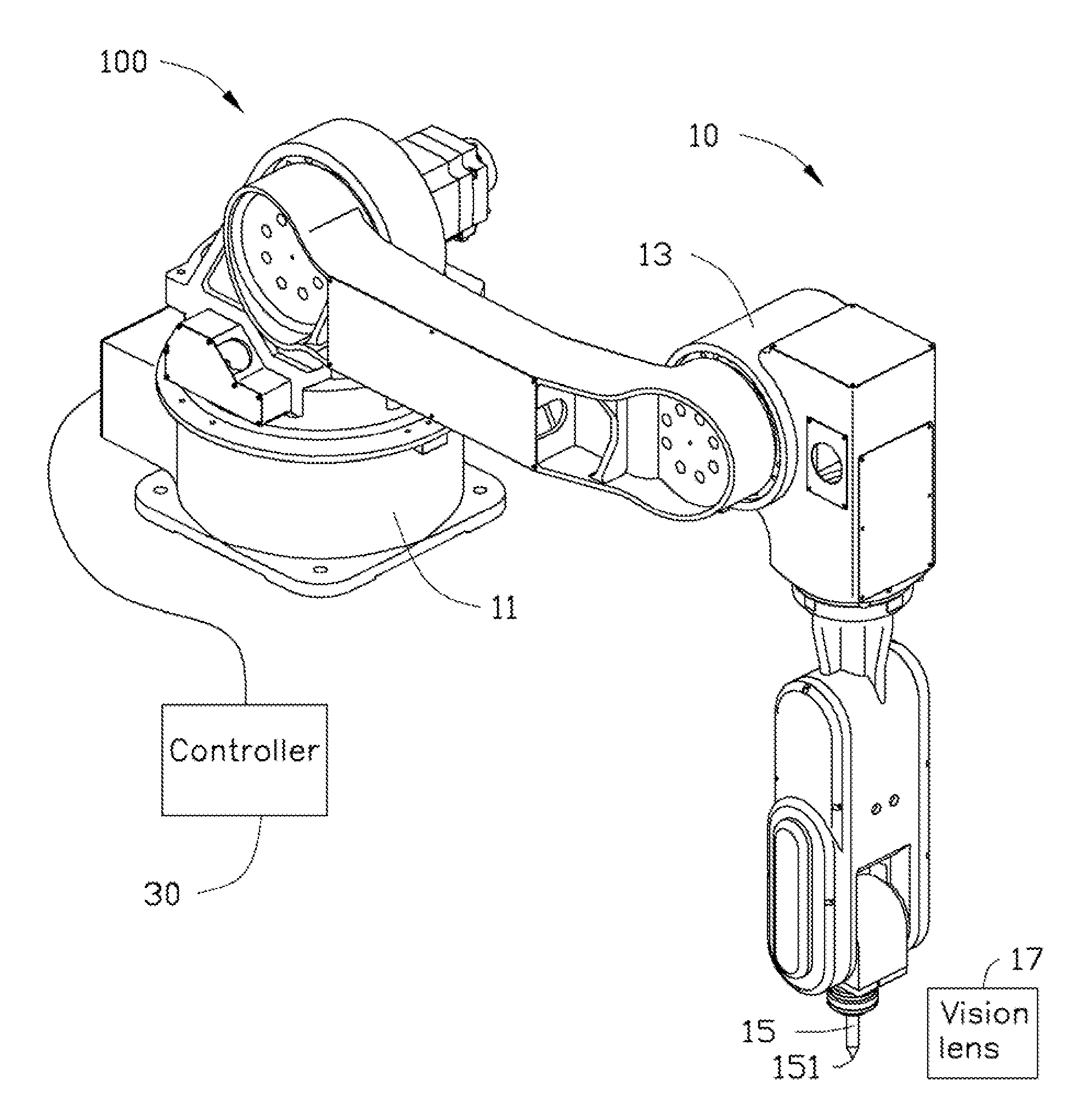
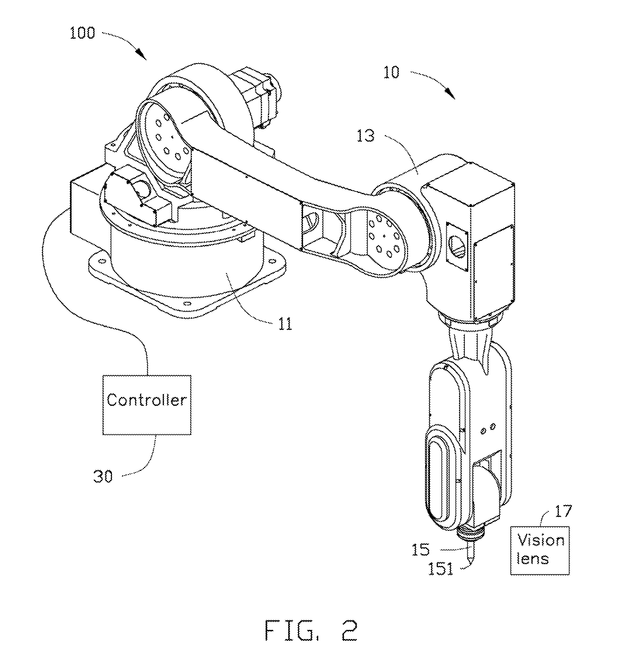
[0011]Referring to FIGS. 2 and 3, an embodiment of a robot manipulator 100 includes a main body 10 and a controller 30 connected to the main body 10. The main body 10 consists of multiple mechanical linkages and includes a base 11 and a drive mechanism 13 that moves the mechanical linkages. The drive mechanism 13 is mounted in the main body 10 and connected with the controller 30. A tool 15 is assembled to a distal end of the main body 10. A vision lens 17 is positioned to one side of the tool 15. The controller 30 includes a preset control software (not shown and not illustrated) and a data storage facility (also not shown and illustrated) installed therein for driving and controlling the drive mechanism 13 to move the tool 15. In the illustrated embodiment, the drive mechanism 13 is a multi-axis drive mechanism controlled by the controller 30. The tool 15 has a defined tool center point (TCP) 151 formed at a distal end of the tool 15. The vision lens 17 is configured for taking a ...


PUM


Abstract

A vision correction method for establishing the position of a tool center point (TCP) for a robot manipulator includes the steps of: defining a preset position of the TCP; defining a preset coordinate system TG with the preset position of the TCP as its origin; capturing a two-dimensional picture of the preset coordinate system TG to establish a visual coordinate system TV; calculating a scaling ratio λ of the vision coordinate system TV relative to the preset coordinate system TG; rotating the TCP relative to axes of the preset coordinate system TG; capturing pictures of the TCP prior to and after rotation; calculating the deviation ΔP between the preset position and actual position of the TCP; correcting the preset position and corresponding coordinate system TG using ΔP, and repeating the rotation through correction steps until ΔP is less than or equal to a maximum allowable deviation of the robot manipulator.

Description

BACKGROUND[0001]1. Technical Field[0002]The present disclosure generally relates to correction methods for robot manipulators, and particularly to a vision correction method for tool center point of a robot manipulator.[0003]2. Description of Related Art[0004]Robot manipulators are used in various industrial fields to fulfill the task requirements for product assembling, welding and other tasks automatically. A robot manipulator of related art may be equipped with a tool, such as a gripper, a cutting device, a glue dispenser or a fixture mounted to a distal end thereof. The tool has a specific defined point, called the Tool Center Point (TCP), that is commanded to move to various positions in the workspace when a robot manipulator performs a task. In use, the positional accuracy of the robot manipulator directly depends on knowing the precise position of the TCP relative to the robot manipulator's distal end. Since the tool may have been mounted to the distal end of the robot manipu...

Claims


Application Information

Patent Timeline
IPC IPC(8): G05B15/00
CPCG05B2219/39026B25J9/1692
Inventor CHIU, LONG-ENFU, SHU-JUNZHAO, GANG
Owner CLOUD NETWORK TECH SINGAPORE PTE LTD
Why Eureka
Try Eureka