Fluid reservoir for a motor vehicle hydraulic brake system

a technology for hydraulic brakes and fluid reservoirs, which is applied in the direction of braking systems, machines/engines, instruments, etc., can solve the problem of saving the need for a cost-intensive timing elemen

Active Publication Date: 2013-02-14
CONTINENTAL TEVES AG & CO OHG
View PDF7 Cites 8 Cited by
  • Summary
  • Abstract
  • Description
  • Claims
  • Application Information

AI Technical Summary

Benefits of technology

[0008]An aim of the present invention is to provide a fluid reservoir improved in this respect.

Problems solved by technology

This saves the need for a cost-intensive timing element.

Method used


Image

  • Fluid reservoir for a motor vehicle hydraulic brake system
  • Fluid reservoir for a motor vehicle hydraulic brake system
  • Fluid reservoir for a motor vehicle hydraulic brake system

Examples


Embodiment Construction

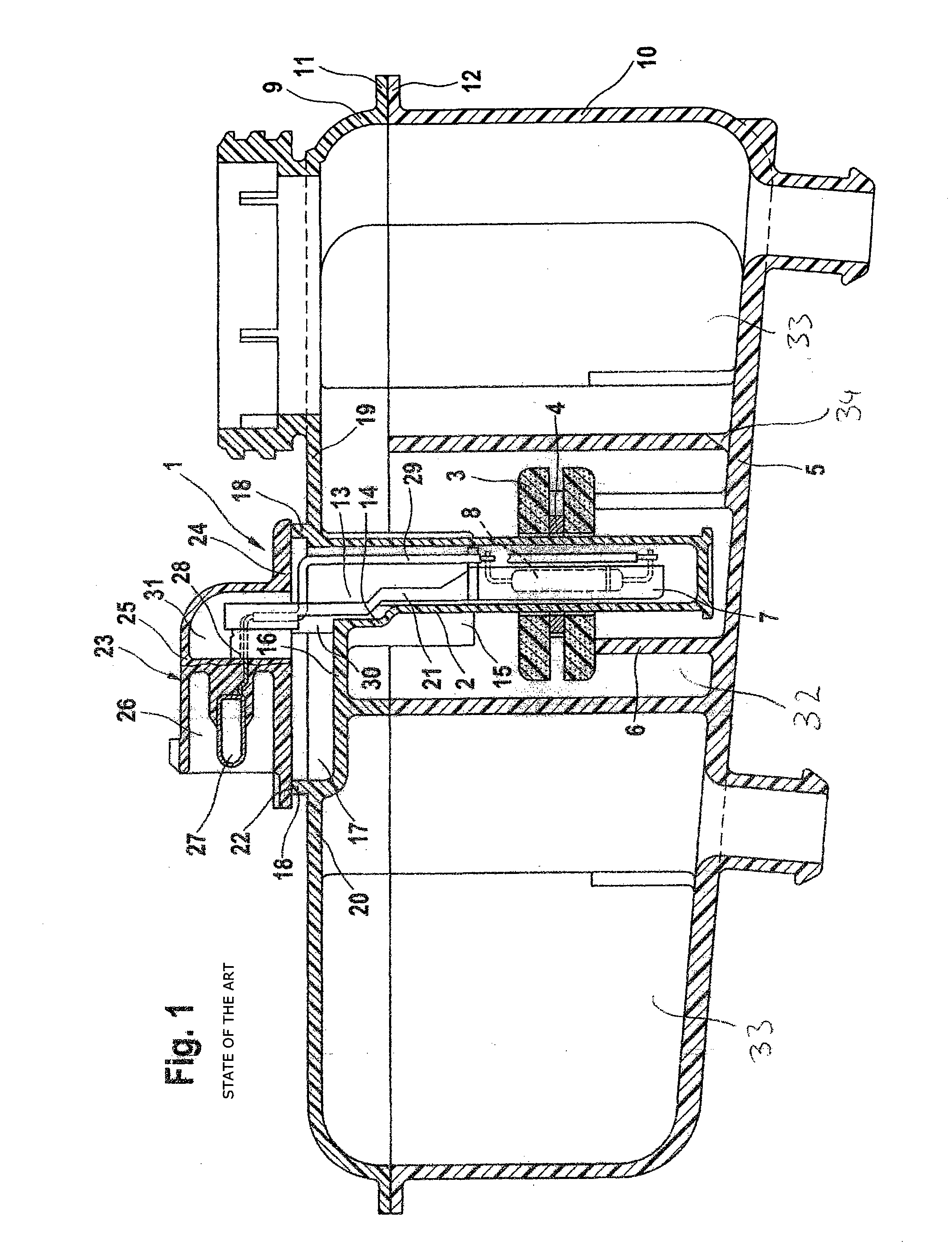
[0024]FIG. 1 shows a known fluid reservoir 1 for brake fluid according to DE 37 16 135 A1, which is incorporated by reference, having a device for monitoring the reservoir filling level. The fluid reservoir 1 is attached, for example, to a master cylinder (not shown) of a vehicle brake system and comprises a guide sleeve 2, which projects into its reservoir interior space and which is closed at its end facing the reservoir interior space. Arranged so that it can be displaced along the guide sleeve 2, which has a circular cross section, for example, is a float 3, which is embodied as a ring, for example, and which constitutes an integral part of a device for monitoring the reservoir filling level. The float 3 carries an annular magnet 4 as magnetic pick-up. A pipe union 6, rising up from the base 5 of the fluid reservoir 1 and in part concentrically surrounding the guide sleeve 2, is intended as stop for the float 3. This stop defines the lowest position of the float 3 in the fluid r...


PUM


Abstract

A motor vehicle hydraulic brake system fluid reservoir for use with an electronic control unit. The hydraulic brake system fluid reservoir has a housing including a reservoir interior space having at least one fluid chamber, and a device for monitoring a reservoir filling level including a switch unit, which with a contact carrier projects into a guide sleeve, which extends into a separate chamber of the reservoir interior space. A sensor element or switch element is arranged on the contact carrier and is operable by a pickup carried on the guide sleeve at a switching point, at which the switch unit generates a signal for the electronic control unit. The separate chamber is connected to the fluid chamber by way of a fluid connection. Valve means are also provided, which serves to control the fluid flow between the separate chamber and the fluid chamber.

Description

CROSS REFERENCE TO RELATED APPLICATIONS[0001]This application is the U.S. National Phase Application of PCT / EP2011 / 056690, filed Apr. 28, 2011, which claims priority to German Patent Application No. 10 2010 028 530.7, filed May 4, 2010, the contents of such applications being incorporated by reference herein.FIELD OF THE INVENTION[0002]The invention relates to a fluid reservoir for a motor vehicle hydraulic brake system, with a housing comprising a reservoir interior space having at least one fluid chamber and a device for monitoring a reservoir filling level comprising a switch unit, which with a contact carrier projects into a guide sleeve, which extends into a separate chamber of the reservoir interior space, a sensor element or switch element arranged on the contact carrier being operable by means of a pickup carried on the guide sleeve at a switching point, at which the switch unit generates a signal for an electronic control unit, and the separate chamber being connected to th...

Claims


Application Information

Patent Timeline
Patent Type & Authority Applications(United States)
IPC IPC(8): G01F23/00
CPCB60T17/225B60T11/26
Inventor NEUMANN, HANS-JURGENTANDLER, PETEROTTMANN, SWEN
Owner CONTINENTAL TEVES AG & CO OHG
Why Eureka
Try Eureka