Apparatus method and system of an ultra sensitivity optical fiber magneto optic field sensor

Inactive Publication Date: 2013-02-14
GOVT OF UNITED STATES OF AMERICA REPRESENTED BY SEC OF THE NAVY CHIEF OF NAVAL RES ONR NRL
View PDF21 Cites 10 Cited by
  • Summary
  • Abstract
  • Description
  • Claims
  • Application Information

AI Technical Summary

Benefits of technology

[0011]An apparatus and system, capable of measuring the magnitude and direction of magnetic fields employing an ultra-sensitive, wideband magneto

Problems solved by technology

They are in general composed of a metallic loop antenna or coil that interacts with the magnetic field; the metal in the antenna or coil results in unacceptably large field perturbations.
As a consequence, the magnetic field measured by the B-dot sensor is not true field, and it is often difficult or impossible to obtain reliable HPM T&E results with these B-dot sensors, particularly in confined spaces.
For low-frequency field characterizations the sensor size then becomes very bulky, and it is unable to measure smaller variations in the field patterns or other patterns near a complex collection of electronic devices.
However, its sensitivity is several orders of magnitude poorer than that of Superconducting qua

Method used


Image

  • Apparatus method and system of an ultra sensitivity optical fiber magneto optic field sensor
  • Apparatus method and system of an ultra sensitivity optical fiber magneto optic field sensor
  • Apparatus method and system of an ultra sensitivity optical fiber magneto optic field sensor

Examples


Embodiment Construction

[0032]Preferred exemplary embodiments of the present invention are now described with reference to the figures, in which like reference numerals are generally used to indicate identical or functionally similar elements. While specific details of the preferred exemplary embodiments are discussed, it should be understood that this is done for illustrative purposes only. A person skilled in the relevant art will recognize that other configurations and arrangements can be used without departing from the spirit and scope of the preferred exemplary embodiments. It will also be apparent to a person skilled in the relevant art that this invention can also be employed in other applications. Further, the terms “a”, “an”, “first”, “second” and “third” etc. used herein do not denote limitations of quantity, but rather denote the presence of one or more of the referenced items(s).

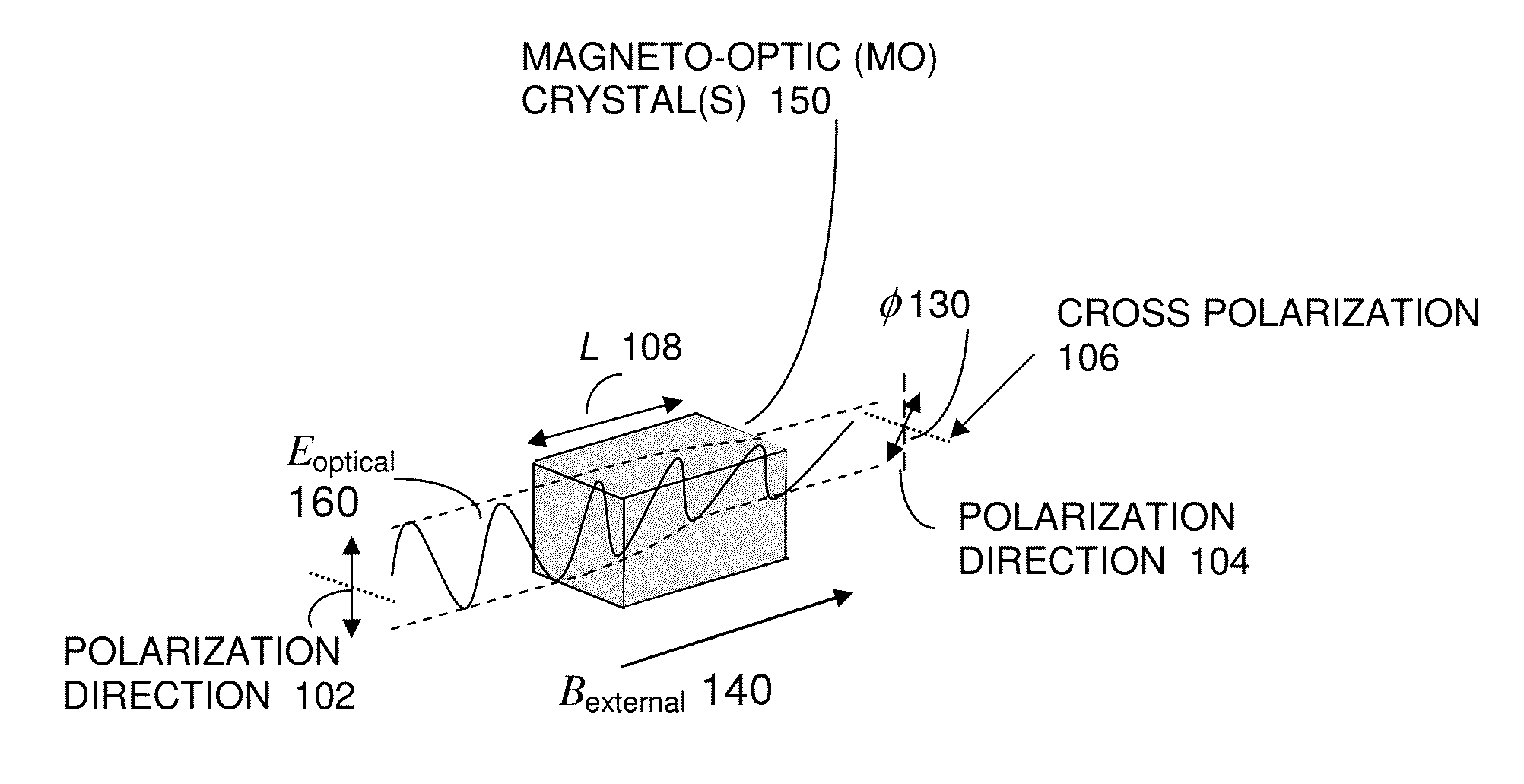
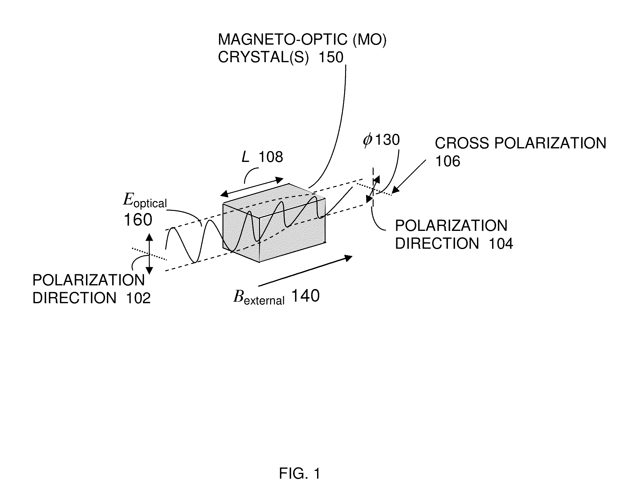
[0033]According to exemplary embodiments, an apparatus and system, capable of measuring the magnitude and direction o...


PUM


Abstract

An apparatus and system, capable of measuring the magnitude and direction of magnetic fields including an ultra-sensitive, wideband magneto optic (MO) sensor having magneto-optic crystals is disclosed herein. The sensor exploits the Faraday Effect and is based on a polarimetric technique. An ultra sensitivity optical-fiber magneto-optic field sensor measures a magnetic field with minimal perturbation to the field, and the sensor can be used for High-power microwave (HPM) test and evaluation; Diagnosis of radar and RF/microwave devices; Detection/measurement of weak magnetic fields (e.g., magnetic resonance imaging); Characterization of very intense magnetic fields (>100 Tesla, for example rail gun characterization); Detection of very low-frequency magnetic fields; Characterization of a magnetic field over an ultra broad frequency band (DC—2 GHz); Submarine detection; and Submarine underwater communication.

Description

RELATED APPLICATIONS[0001]Pursuant to 35 USC §120, the present application is related to and a continuation of and claims the benefit of priority to U.S. Non-Provisional patent application Ser. No. 12 / 829,298, now published application US Publication No. 2010-0264904 Apparatus and System for a Quasi Longitudinal Mode Electro Optic Sensor for High Power Microwave Testing, filed on Jul. 1, 2010, which is herein incorporated by reference in its entirety, which is a continuation of related U.S. Non-Provisional patent application Ser. No. 12 / 205,766, now U.S. Pat. No. 7,920,263, Apparatus and System for Electro Magnetic Field Measurements and Automatic Analyses of Phase Modulated Optical Signals from Ellectrooptic Devices. Also, pursuant to 35 USC §119(e), the present application is related to and claims priority to U. S. Provisional Application for Patent 61 / 522,908, Apparatus Method and System of an Ultra Sensitivity Optical Fiber Magneto Optic Field Sensor, filed on Aug. 12, 2011, whi...

Claims


Application Information

Patent Timeline
IPC IPC(8): G01R33/032
CPCG01R33/0327G01R33/032G01R33/323
Inventor WU, DONG HOGARZARELLA, ANTHONY
Owner GOVT OF UNITED STATES OF AMERICA REPRESENTED BY SEC OF THE NAVY CHIEF OF NAVAL RES ONR NRL
Why Eureka
Try Eureka