All-fiber current monitoring device based on Faraday effect

A Faraday effect and current monitoring technology, which is applied in the direction of measuring devices, using optical devices to transmit sensing components, voltage/current isolation, etc., can solve the problems of low beam deflection accuracy, high economic cost of two photodetectors, and current monitoring results. Inaccurate and other problems, to achieve the effect of small electromagnetic interference, high accuracy, and reduce economic costs

Inactive Publication Date: 2010-08-04
HARBIN INST OF TECH
View PDF3 Cites 8 Cited by
  • Summary
  • Abstract
  • Description
  • Claims
  • Application Information

AI Technical Summary

Problems solved by technology

[0003] The present invention provides an all-fiber current sensor based on the Faraday effect in order to solve the problems of inaccurate current monitoring results and high economic cost of using two photodetectors in existing current monitoring instruments that use digital signals to judge the beam deflection accuracy is low. monitoring device

Method used


Image

  • All-fiber current monitoring device based on Faraday effect
  • All-fiber current monitoring device based on Faraday effect

Examples


specific Embodiment approach 1

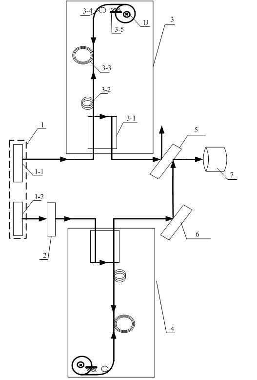
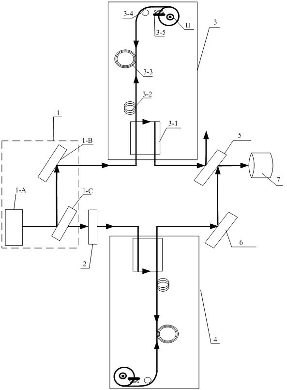
[0008] Specific implementation mode one: according to the instructions attached figure 1 This embodiment is described in detail. The Faraday effect-based all-fiber current monitoring device described in this embodiment includes a light source system 1, a half-wave plate 2, a first fiber optic transformer 3, a second fiber optic transformer 4, a first half-wave The anti-half mirror 5, the second total reflection mirror 6 and the photodetector 7, the second fiber optic transformer 4 have the same structure as the first fiber optic transformer 3, and the light source system 1 emits the first light beam to the signal input of the first fiber optic transformer 3 end, the signal output end of the first optical fiber transformer 3 outputs the first polarized light to the first half mirror 5, and the first half mirror 5 outputs the transmitted light signal to the photodetector 7; the light source system 1 Also send the second light beam to the half-wave plate 2, the second light beam ...

specific Embodiment approach 2

[0009] Embodiment 2: This embodiment is a further description of Embodiment 1. The first fiber optic transformer 3 and the second fiber optic transformer 4 described in Embodiment 1 are two identical optically active crystals.

specific Embodiment approach 3

[0010] Embodiment 3: This embodiment is a further description of Embodiment 1. The first fiber optic transformer 3 described in Embodiment 1 includes a single-mode fiber coupler 3-1 and a fiber optic polarizer 3-2. , polarization-maintaining optical fiber 3-3, λ / 4 wave plate 3-4 and the first total reflection mirror 3-5, the signal input end of the single-mode optical fiber coupler 3-1 is the signal input end of the first optical fiber transformer 3, The first light beam emitted by the light source system 1 is input to the signal input end of the fiber polarizer 3-2 through the single-mode fiber coupler 3-1, and the fiber polarizer 3-2 outputs linearly polarized light to the polarization maintaining fiber 3- 3, the polarization maintaining fiber 3-3 outputs two beams of orthogonally polarized light to the signal input end of the λ / 4 wave plate 3-4, and the λ / 4 wave plate 3-4 outputs left-handed circularly polarized light And right-handed circularly polarized light to the first...


PUM


Abstract

The invention discloses an all-fiber current monitoring device based on a Faraday effect, which relates to the field of current monitoring and solves the problems of inaccurate current monitoring results because of low accuracy rate of light beam deflection judged by traditional current monitoring equipment by using a digital signal and high economic cost by using two photo detectors. The device comprises a light source system, a half-wave plate, a first fiber mutual inductor, a second fiber mutual inductor, a first semi-reflecting semi-transmitting mirror, a second total reflection mirror and a photo detector, wherein the light source system emits a first light beam to the first fiber mutual inductor and a first polarized light output by the first fiber mutual inductor is input to the photo detector through the first semi-reflecting semi-transmitting mirror; the light source system further emits a second light beam, the second light beam is emitted to the second fiber mutual inductor after being transmitted through the half-wave plate, a second polarized light output by the second fiber mutual inductor is input to the first semi-reflecting semi-transmitting mirror through the second total reflection mirror and the first semi-reflecting semi-transmitting mirror outputs reflected lights to the photo detector. The invention is applied to current monitoring.

Description

technical field [0001] The invention relates to the field of current monitoring, in particular to an all-optical fiber current monitoring device based on the Faraday effect. Background technique [0002] The current optical current monitoring instrument is a photodetector in a fiber optic current transformer. Because the dark current in the photodetector changes under the current mutual inductance, the light beam passing through the two photodetectors changes. The detector then compares the received two beams of light with digital signals. If there is a difference between the two digital signals, it means that the current is abnormal during the transmission of light. However, the cost of using two photodetectors is high, and they are subject to strong electromagnetic interference during use, and the errors that occur after the optical signal is converted into an electrical signal are greatly affected, so the accuracy of the two beam deflections obtained is low, making the cu...

Claims


Application Information

Patent Timeline
Patent Type & Authority Applications(China)
IPC IPC(8): G01R19/00G01R15/24G01D5/30
Inventor 郭志忠申岩张国庆于文斌路忠锋吴磊
Owner HARBIN INST OF TECH
Why Eureka
Try Eureka