Method and Device for Determining the Speed of Travel and Coordinates of Vehicles and Subsequently Identifying Same and Automatically Recording Road Traffic Offences

a technology of speed and coordinates, applied in the field of traffic control systems, can solve the problems of reducing the service characteristics of prototype methods, high probability of speed-violator identification, and prototype methods

Active Publication Date: 2013-02-14
OBSHCHESTVO S OGRANICHENNOJ OTVETSTVENNOSTJU KORPORATSIJA STROJ INVEST PROEKT M
View PDF28 Cites 39 Cited by
  • Summary
  • Abstract
  • Description
  • Claims
  • Application Information

AI Technical Summary

Benefits of technology

[0017]to develop a method for determining the speed and coordinates of vehicles and a device for its implementation, which will decrease the probability of the false identification of a speed-violating vehicle in the automatic speed violation recording systems;
[0020]This will drastically reduce the costs to build and service elevated structures used for the installation of speed monitoring devices.
[0022]A novel feature of the developed method is that the mentioned pulses are emitted by a radar simultaneously with capturing the same road section by a panoramic video camera. The video camera is calibrated so that the real coordinates of distances from the video camera to the corresponding sections on the road are assigned to each row element Yi and each column element Xi of the video camera matrix. Moreover, based on the pulses received by the radar, the distance and speed are calculated not for one but for all the vehicles, which are at the moment on the selected road section hundreds of meters long; using the image of vehicles captured by the video camera, the coordinates and speeds of the same vehicles, which are in the a frame, are calculated independently and simultaneously. Then, data streams containing the speed and coordinate values for all the vehicles, which are at the moment on the selected road section, and received by the radar and the video camera independently of each other are compared. To get the reliable metrological speed and coordinate values, the radar data are used. Each vehicle violating traffic rules is tracked until the license plate is recognized. Then the image frame of the speed-violating vehicle is generated; the easily readable license plate, date, time and recorded speed and / or coordinate values are displayed in this frame, which allows automatic recording of traffic violations.
[0025]A novel feature of the developed device is that the radar has a signal processing module, which calculates the speeds and distances of all the vehicles moving along the selected road section. The device includes a panoramic video camera capturing a road section 40-50 meters to hundreds of meters long, which is connected to a control and data processing unit. The data processing unit is equipped with software to synchronize the radar and panoramic video camera, compare the data streams obtained from the radar and video camera, provide the reliable metrological measurements of the violating vehicles' speed and coordinates and transmit the data for automatic recording of traffic violations.

Problems solved by technology

Assuming that the distances are comparable, the area of a vehicle moving parallel to the monitored one is several times larger, while its speed exceeds the allowed speed limit, then we are in a situation where a monitoring device will send a signal that the vehicle moving within the monitored area has exceeded the speed limit If the probability of such events is high (heavy traffic flow), the number of erroneously recorded speed violations will be significant, which will substantially reduce the service characteristics of the prototype method.
The above analysis suggests that the prototype method has a grave disadvantage, namely, a high probability of the erroneous speed-violator identification.
This makes the prototype method unsuitable for use on a multi-lane road with a heavy traffic flow.

Method used


Image

  • Method and Device for Determining the Speed of Travel and Coordinates of Vehicles and Subsequently Identifying Same and Automatically Recording Road Traffic Offences
  • Method and Device for Determining the Speed of Travel and Coordinates of Vehicles and Subsequently Identifying Same and Automatically Recording Road Traffic Offences
  • Method and Device for Determining the Speed of Travel and Coordinates of Vehicles and Subsequently Identifying Same and Automatically Recording Road Traffic Offences

Examples


Embodiment Construction

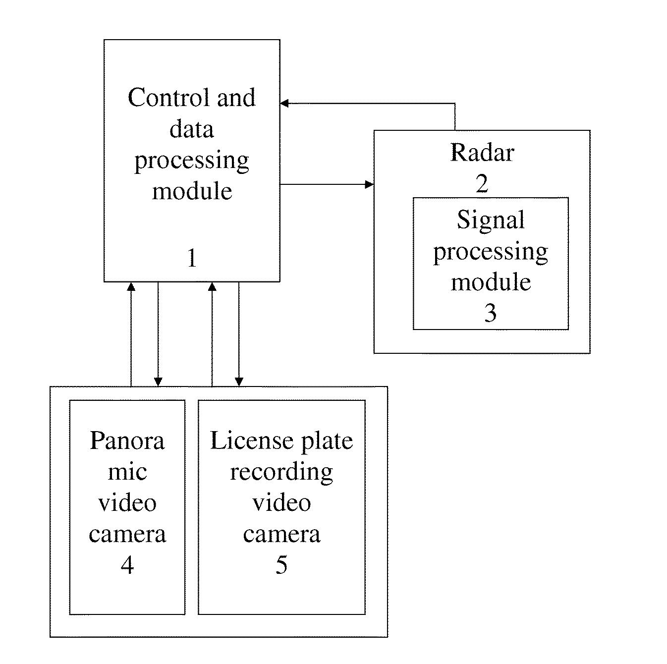
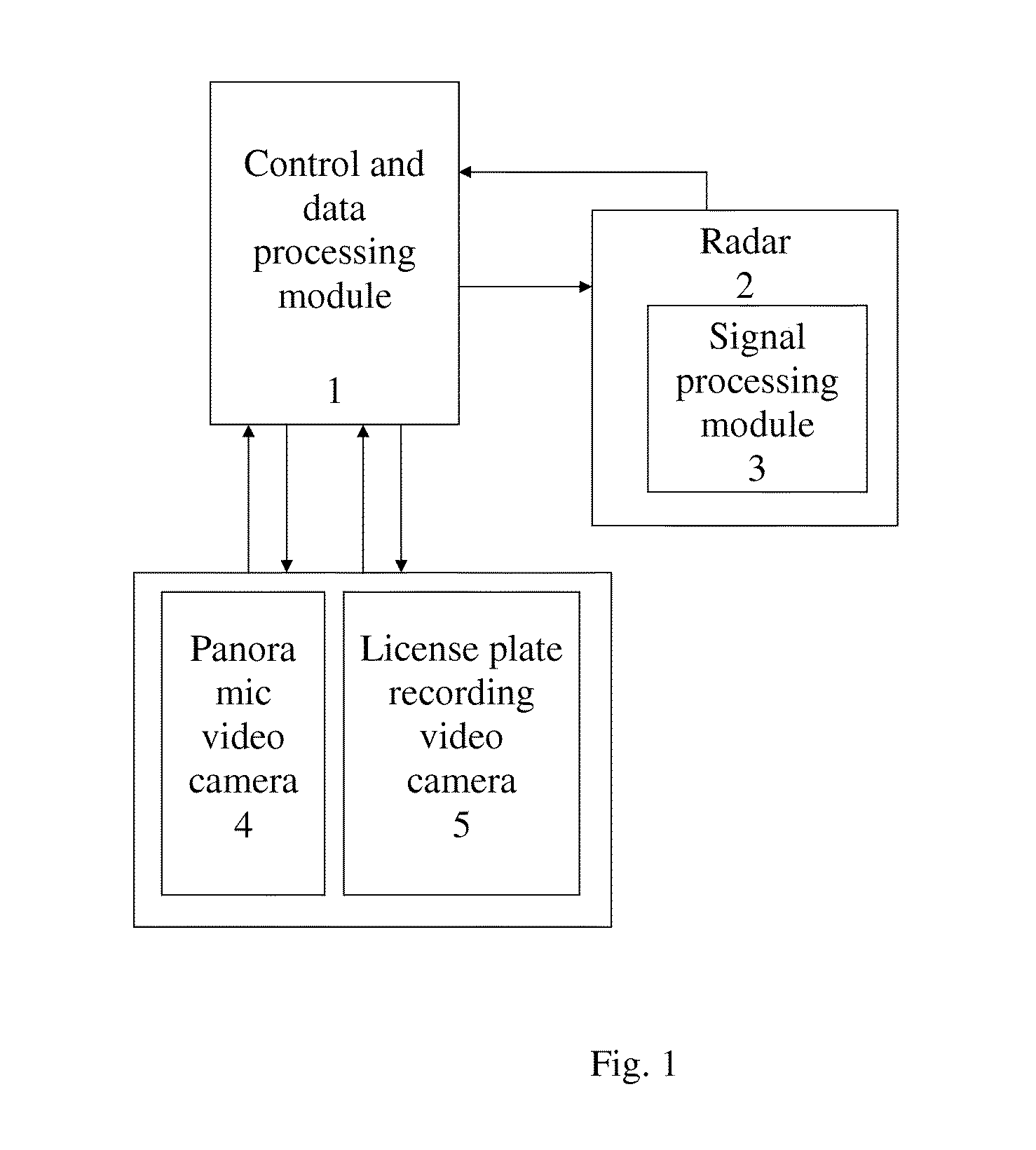
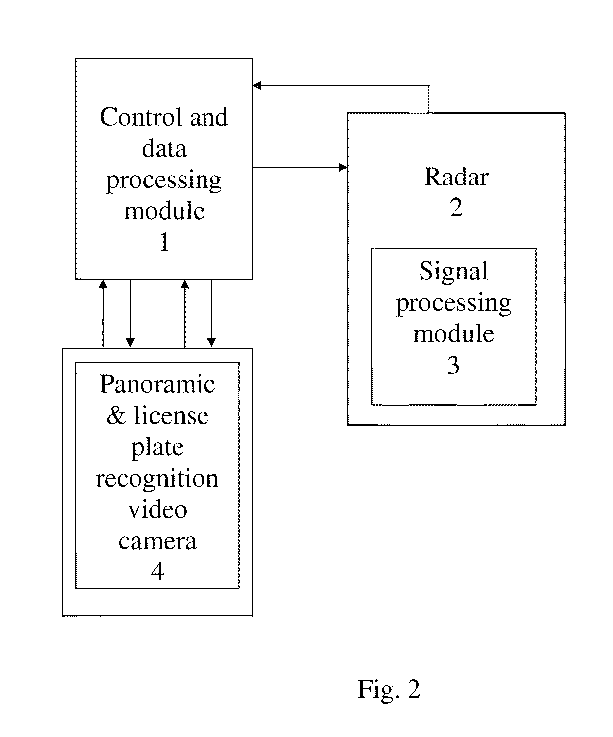
[0035]Control and data processing module 1 is a computer with software which:[0036]controls radar 2 and video cameras 4, 5;[0037]receives signals from video cameras 4, 5;[0038]receives data from signal processing module 3 (signals from radar 2);[0039]generates data streams related to the coordinates and speeds of the vehicles which are in the frame captured by video camera 4;[0040]compares the data streams from module 3 of radar 2 and from video camera 4;[0041]transmits data to the central traffic control station (not shown) for the automatic recording of traffic violations.

[0042]The specific embodiment of control and data processing module 1 is based on the Intel Pentium M processor. Module 1 features high performance, comparatively low power consumption (˜40 W), is structurally protected against mechanical impacts by a special damping system and is intended to operate at −40 to +60° C. (see FIG. 5).

[0043]A classic monopulse radar providing digital storage and processing of the rec...


PUM


Abstract

The automatic system makes it possible to reduce the probability of error when identifying the vehicle of an offender, increases the length of a speed limit monitoring zone to several hundreds / thousands of meters, and makes it possible to cut expenditure on the construction and maintenance of gantries for the installation of speed limit monitoring devices. A method for the combined processing of signals from a radar and a panoramic video camera is proposed, in which data flows from the video camera and the radar are independently obtained, after which they are compared and data about the speed and coordinates are obtained with little probability of error in identifying the vehicle of an offender. The device for realizing the method comprises a radar with a signal processing module to calculate the speed and distance of all vehicles on a chosen section of road, and a panoramic video camera.

Description

RELATED APPLICATIONS[0001]This Application is a Continuation application of International Application PCT / RU2010 / 000048 filed on Feb. 8, 2010, which is incorporated herein by reference in its entirety.FIELD OF THE INVENTION[0002]The invention relates to traffic control systems and more specifically to methods and devices for monitoring compliance with road traffic rules, including speed.BACKGROUND OF THE INVENTION[0003]To control compliance of vehicles moving in a stream with a speed limit and automatically record violations, it is necessary to measure the speed and coordinates of a vehicle and, in the case of a speed limit violation, identify it with a required, rather high probability. Speed is generally measured by radars, whose principle of speed measurement is based on the Doppler effect, or by laser devices (lidars), whose principle of speed measurement is based on an assessment of the time intervals between emitted and received (as reflected from the vehicle) pulses, followed...

Claims


Application Information

Patent Timeline
Patent Type & Authority Applications(United States)
IPC IPC(8): H04N7/00
CPCG08G1/054G08G1/0175G08G1/017G07C5/08
Inventor OSIPOV, SERGEY KONSTANTINOVICHMALINKIN, ALEKSEY YURIEVICH
Owner OBSHCHESTVO S OGRANICHENNOJ OTVETSTVENNOSTJU KORPORATSIJA STROJ INVEST PROEKT M
Why Eureka
Try Eureka